What's new
What's new

Help with wiring a new Baldor 1hp single phase motor to my rotary switch

dago

Plastic
Joined
Oct 22, 2022
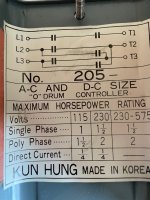
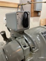
I have a South Bend Heavy 10 lathe with a Kun Hung rotary drum switch that came new with the lathe. I purchased a new Baldor 1hp motor for the lathe but am having trouble figuring out how to wire motor to switch. I know there have been simular post but no one had the same wiring or switch as mine. I would appreciate any help i could get.
thank you,
DagoIMG_0079.jpgIMG_0098.jpgIMG_0131.jpg
 

dago

Plastic
Joined
Oct 22, 2022
I should have mentioned 220 voltage, sorry about that.
this is a few more pic of the switch and motor.IMG_0134.jpgIMG_0133.jpg
 

michiganbuck

Diamond
Joined
Jun 28, 2012
Location
Mt Clemens, Michigan 48035

I like to revere with the handle going perhaps in the direction the spindle would go...what would seem logical if the for & rev was not noted..

It really seems odd the motor plate does not show. Is the motor reversible?
 
Last edited:

dago

Plastic
Joined
Oct 22, 2022
Another approch that minimizes the interconnects between switch and motor:


I kile to revere with the handle going perhaps in the direction the spindle would go...what would seem logical if the for & rev was not noted..

It really seems odd the motor plate does not show. Is the motor reversible?
yes this is a new Baldor reversable motor. it says on the name plate what wires to reverse to get that. i just don't understand what wires to bring to the switch from motor and how to wire the switch.
 

kitno455

Titanium
Joined
Jul 9, 2010
Location
Virginia, USA
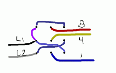
This switch is really designed for switching three phase motors, but we can make it work with 220 single phase. The idea here is that we switch the position of leads 1 and 4, while keeping lead 8 on the same hot wire. This requires a jumper inside the switch, which I have drawn in purple. If this rotates in the incorrect direction, you can swap 5 and 8, or change that purple jumper to connect L1 to L3. Give this a shot, and let us know how it works.

allan

KH-baldor-220.gif
 

jim rozen

Diamond
Joined
Feb 26, 2004
Location
peekskill, NY
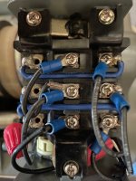
Open up the drum switch and take a photo. It's probably the standard three pole, double throw, center off unit with the jumpers pre-installed. If that's the case it maps exactly to the diagram i showed. This works because the run winding is centertapped - The start winding circuit ties to the centertap and depending on which hot line the *other* side ties to, it reverses the phase sense of the start winding with respect to the run winding. You have the complete motor schematic with all the vital connections identified.

This connection of course only works for dual voltage motors run on 240.
 

dago

Plastic
Joined
Oct 22, 2022
This is a picture of the switch wired to the old Century motor on my lathe. unfortunately the Century wiring diagram is different from Baldor wiring and i am at a loss on how to wire new motor to this switch.IMG_0095.jpg
 

kitno455

Titanium
Joined
Jul 9, 2010
Location
Virginia, USA
Jim is right about the 3pdt, the switch diagram did not indicate that there were 9 terminals. But, you still would have to change those soldered jumpers to use his diagram.
allan
 
Last edited:

kitno455

Titanium
Joined
Jul 9, 2010
Location
Virginia, USA
Here is an image which shows how to connect the motor to the switch. Input power comes in on the outside terminals (either side will work) and leaves from the center terminals. The blue jumpers are already on the switch. The purple jumper you'll have to add, but you've already got a piece you can re-use on the switch now. You'll need to connect 2, 3 and 5 at the motor.
3pdt-220-baldor.gif
 

dago

Plastic
Joined
Oct 22, 2022
Allan,
The way my switch is wired now for the other motor is the power is coming in from the center terminals and then to the motor on the outside terminals.
There is a jumper on the inside terminal i guess to bring power to the other terminal for L1 and T1.
Could i do mine the same way and bring in the red,yellow and blue wires to the outside terminals?
Sorry for sounding stupid it is just that I don't understand this as well as ya'll do.
thank you for all this help,
John
 

dago

Plastic
Joined
Oct 22, 2022
my reason for this is that the middle terminals are the off position and throwing switch to right or left is forward and reverse. i was thinking that if the power goes to outside poles then the switch would not make contact there for power on the other side when i turn switch to go the other direction. the switch seems to make contact with the middle poles and outside poles depending on which way i turn the forward or reverse lever.
John
 

kitno455

Titanium
Joined
Jul 9, 2010
Location
Virginia, USA
It is very rare that I find someone who declares themselves to be clueless and asks for help, who then argues with the help given. Give my diagram a shot. Worst case, I got something wrong, your circuit breaker trips, and you've wasted a few minutes. Best case, you are up and running.
 

kitno455

Titanium
Joined
Jul 9, 2010
Location
Virginia, USA
I'm sorry, that last post was mostly me being argumentative, not you. I'll try to educate instead. Do you see the existing blue jumper wires on the switch? When you connect power to either column of outside terminals, you are effectively connecting to both. Hence, you can take the output from the center.

allan
 

kitno455

Titanium
Joined
Jul 9, 2010
Location
Virginia, USA
OK, I stared at it for a few minutes, and you could move the inputs and jumper to the center, and the outputs to one side. The circuit would behave the same. This configuration does have the added benefit of having slightly less of the switch hot in the off position. I guess that means you can leave the switch as-is, assuming you can identify which black wire is which at the motor end.

Nice job advocating for yourself. And as usual, I've gone from cocksure to apologizing in only three posts :)

allan
 

dago

Plastic
Joined
Oct 22, 2022
Thank you again, allan, for staying with me on this. I have stared at it for so long myself that i was not sure of anything anymore. i will run new wires to switch that match the colors in your drawing so as to not get mixed up. Also, you have reassured me that i won't blow up my motor it would just trip circuit breaker if i wired something wrong. Looking at your first diagram you made for me it looks like you had it anyway i am going to just connect to the center screws instead of L1 and L2 with the jumper for power.
it will take me some time to unhook and take the old motor out before installing the new one but hopefully i can do it in a day.
Again, thanks for all your help and I will let you know how it came out.
John


Top