Largest Manufacturing Technology Community on the Web
Stay Connected:
You are using an out of date browser. It may not display this or other websites correctly.
You should upgrade or use an alternative browser.
You should upgrade or use an alternative browser.
Rotary Phase Converter Designs and Plans
- Thread starter Milacron
- Start date
- Replies 200
- Views 461,943

StickShifter
Plastic
- Joined
- Apr 1, 2009
- Location
- Ypsilanti, MI
My 20HP RPC
I thought I'd share my design since it is based off a few that I found in this thread. It is supplying power to my Bridgeport VMC800 and seems to be working fine. I designed it so it will fail safe in case of a power outage by staying off even if the power comes back on. One thing to note is that I did not use the line fuses.


I thought I'd share my design since it is based off a few that I found in this thread. It is supplying power to my Bridgeport VMC800 and seems to be working fine. I designed it so it will fail safe in case of a power outage by staying off even if the power comes back on. One thing to note is that I did not use the line fuses.


DerekW4203
Plastic
- Joined
- Sep 16, 2015
My phase converter
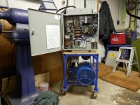
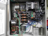
Here are some pictures of the phase converter I built a while back. It is using a 10hp motor that I got off an old air compressor that was going to be scrapped. It is based off the Fitch design but I simplified it by using 110v contactors and eliminating the 24v transformer. The thing I really like about this design is that it is self starting once the start switch is pushed so there is no need get the motor rotating manually. It is also designed so that if it ever looses power even momentarily the latching contactor will open shutting down the system and it won't restart with out user input.


Here are some pictures of the phase converter I built a while back. It is using a 10hp motor that I got off an old air compressor that was going to be scrapped. It is based off the Fitch design but I simplified it by using 110v contactors and eliminating the 24v transformer. The thing I really like about this design is that it is self starting once the start switch is pushed so there is no need get the motor rotating manually. It is also designed so that if it ever looses power even momentarily the latching contactor will open shutting down the system and it won't restart with out user input.
rpc to run in the uk with single live
hi as with most newbies ive been looking through loads of posts trying to pull together some ideas and ive got a drawing together but i would just like peoples opinions on if ive got it right and what sort of sizes of components do i need such as does the run cap need to be oil filled. also should there be run caps between legs
thanks guys
Last edited:
challenger
Stainless
- Joined
- Mar 6, 2003
- Location
- Hampstead, NC-S.E. Coast
Every bit of Information you need is in this thread. Read through it like most did and you will get a running unit.
Galaxy S4, Slimkat
If I wasn't married I'd quit fishing")
Galaxy S4, Slimkat
If I wasn't married I'd quit fishing
jappietoutou
Aluminum
- Joined
- Dec 2, 2015
- Location
- Montreal
Hello !
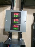
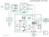
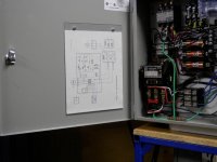
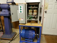
Here are some pictures and a diagram of my 7.5 HP Phase converter.
I built it to supply power to a 5 HP Surface grinder I bought at an auction, just for the fun of rebuilding it.
I followed this procedure to balance the voltages. http://www.practicalmachinist.com/FitchWConverter.pdf
The surface grinder is working on 575 v, which is a common voltage for industrial motors here in Canada.
During construction, I had a Mentor going by the name of SAF, his help and guidance on using 600 volts was invaluable, particularly on safety issue. And of course this forum, where you can find answers to all yours questions.
I will post more on the other post/thread I had started earlier: 240 v to 575 v 3 phase converter project.
Attachments
I'm trying to leverage a previous set up that was using capacitors to start an idler motor to be used as a rotary phase converter to provide a small wood shop with three phase power from two phase power. I've been able to work with the previous owner who worked with a master electrician years ago to create the set-up shown on the first page of the file in the link (quite slick). The previous owner just tapped off the idler motor to one cable he used with a female connector on the end to run one piece of equipment at a time. I would like to add a breaker panel to 1) Protect other equipment, 2) Install several outlet boxes so that we can run two pieces of equipment at the same time, or at least wire all equipment to be plugged in without having to move stuff around the shop to the motor. The other equipment has much smaller hp, so the 10hp idler even on 2/3 efficiency is plenty.
My question is mostly how to wire from the idler motor to a 3 phase breaker panel. The second page of the file in the link shows the configuration as I see it. Is that correct? What about the rest of the wiring, does this look okay as well?
Link to images/diagrams: https://1drv.ms/b/s!AmHg-rUAwxpdtSChBr3sxhL1-qkg
Don Gitzel
Aluminum
- Joined
- Jul 25, 2017


Don Gitzel
Aluminum
- Joined
- Jul 25, 2017
Here are pics of a few I have made. The vertical mount motor is on a brake drum. lol


THIS IS NOW A BAD LINK
bigoldiron.com
bigoldiron.com
Ox
Diamond
- Joined
- Aug 27, 2002
- Location
- West Unity, Ohio
I can't see your photos as you're not prepared to pay on upgrading for 3rd party
-----------------------
Think Snow Eh!
Ox
2Slow
Hot Rolled
- Joined
- Jun 26, 2006
- Location
- South East Michigan, USA
This design is for a static phase converter. There is not a lot of info on static phase converters here and some people may find this useful. Building a RPC takes about the same effort, and will run your machine cooler and with more power, so that is normally a better decision. If you have an application that wants a box with no moving parts wired before the input of your 3ph machine, this should work.
If it is too far outside the intent of this thread, moderator please move or delete this post.
This converter was sized for a 3HP geared head lathe where the motor is always attached to the spindle. (No clutching) Since they would be cycled every time the lathe was started, I used oil filled run capacitors in all locations (even the Start caps) to allow for frequent starts and stops. In top gear, 2,000RPM, the lathe motor takes a little while to get up to speed (like 1-2 seconds) and growls a little bit just before getting to full speed. All lower gears start nearly instantaneously, without any noise.
There is a total of 300uF starting the lathe motor. 250 uF (5x 50uF Caps wired in parallel) is switched in and out with the Steveco 90-65 Potential Relay, and the other 50uF is always connected providing starting assistance and balance once running.
With the lathe motor running the voltages were:
Unlike an RPC where line voltage into the converter is switched to activate, this design is intended to activate when the load is switched on. That is the reason for the small 120V coil relay that is in-between the reference voltage and pin 5 of the potential relay. Without it, the potential relay would chatter when the converter had power and there was no load. The small relay opens the connection between the reference pin and L1 until there is a load, when it closes.
Care was taken to ensure that the third leg was not incorporated into any of the lathe control power.
Components used:
Steveco 90-65 Potential Relay - Surplus
6x 50 uF 370V rated oil filled run caps (5 of them used as starting caps)
Small DPDT 120V coil relay. Small 120V coil relay - Omron LY2-UA-006244 (A SPST NO 120V coil relay, could be substituted as the other poles are not used, I bought the one I used on Amazon)
500 ohm 10W resistor
16,500 Ohm 2W resistor
The wiring diagram is below. Essentially it mimics the starting circuit of a RPC that utilizes a potential relay with the NO contacts of the small 120V coil relay in series with the reference voltage

If you want to read through the saga of figuring out how to make a static converter that would work with load switched, this is the thread.
If it is too far outside the intent of this thread, moderator please move or delete this post.
This converter was sized for a 3HP geared head lathe where the motor is always attached to the spindle. (No clutching) Since they would be cycled every time the lathe was started, I used oil filled run capacitors in all locations (even the Start caps) to allow for frequent starts and stops. In top gear, 2,000RPM, the lathe motor takes a little while to get up to speed (like 1-2 seconds) and growls a little bit just before getting to full speed. All lower gears start nearly instantaneously, without any noise.
There is a total of 300uF starting the lathe motor. 250 uF (5x 50uF Caps wired in parallel) is switched in and out with the Steveco 90-65 Potential Relay, and the other 50uF is always connected providing starting assistance and balance once running.
With the lathe motor running the voltages were:
238 L1 to L2
225 L1 to L3
240 L2 to L3
225 L1 to L3
240 L2 to L3
Unlike an RPC where line voltage into the converter is switched to activate, this design is intended to activate when the load is switched on. That is the reason for the small 120V coil relay that is in-between the reference voltage and pin 5 of the potential relay. Without it, the potential relay would chatter when the converter had power and there was no load. The small relay opens the connection between the reference pin and L1 until there is a load, when it closes.
Care was taken to ensure that the third leg was not incorporated into any of the lathe control power.
Components used:
Steveco 90-65 Potential Relay - Surplus
6x 50 uF 370V rated oil filled run caps (5 of them used as starting caps)
Small DPDT 120V coil relay. Small 120V coil relay - Omron LY2-UA-006244 (A SPST NO 120V coil relay, could be substituted as the other poles are not used, I bought the one I used on Amazon)
500 ohm 10W resistor
16,500 Ohm 2W resistor
The wiring diagram is below. Essentially it mimics the starting circuit of a RPC that utilizes a potential relay with the NO contacts of the small 120V coil relay in series with the reference voltage
If you want to read through the saga of figuring out how to make a static converter that would work with load switched, this is the thread.
thermite
Diamond
- Joined
- Sep 21, 2011
This design is for a static phase converter.
..
If it is too far outside the intent of this thread, moderator please move or delete this post.
A STICKY is made a sticky to cover the topic in its title.
This thread is specifically for ROTARY Phase Converters.
Please read the Topic Title.
You should be able to delete it yourself and save a Moderator the bother.
mrbreezeet1
Aluminum
- Joined
- Dec 5, 2008
- Location
- Wheeling WV USA
Subscribed
Sent from my MotoG3 using Tapatalk
Sent from my MotoG3 using Tapatalk
I see most of these have been built with the potential relay to control the starting capacitor. However, I have seen some designs that use a momentary switch, in conjunction with the start button, to put the starting cap in the circuit for some time.
I am planning on using a rotary switch - 3 position I think. Like a start switch in a car with the far right, momentary, spring return to the center.
Thoughts?
I am planning on using a rotary switch - 3 position I think. Like a start switch in a car with the far right, momentary, spring return to the center.
Thoughts?
Hopefuldave
Cast Iron
- Joined
- Apr 1, 2010
- Location
- Surrey, England
Hi Steve,
I used a momentary switch to a low-current two-pole relay, one pole feeds the start cap's contactor coil, the second the run contactor's coil which is held in by one of its aux contacts - so hold the button in and both operate, and power is applied via the run contactor which latches thanks to the aux contacts, start cap is connected by its contactor until you let go of the start button and the two-pole drops out. Works well!
Dave H. (the other one)
Don Gitzel
Aluminum
- Joined
- Jul 25, 2017


Similar threads
- Replies
- 16
- Views
- 478
- Replies
- 7
- Views
- 317
- Replies
- 25
- Views
- 734
- Replies
- 39
- Views
- 1K