What's new
What's new

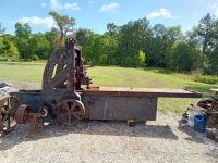
Whitcomb planer

M.B. Naegle

Titanium
Joined
Feb 7, 2011
Location
Conroe, TX USA
This plainer looks very close to those in my 1920's Whitcomb Blaisdell/Becker catalog (need to get it scanned and uploaded to vintage machinery...), but does lack a few advancements such as a two speed counter-shaft, and outboard support of the pulleys. By the 1920's, they no longer had the makers info cast into the base casting and only had it on the top rail. Whitcomb and Blaisdell got together in 1905. Not sure if they immediately updated the pattern lettering though, but by the 1920's when they merged with Reed-Prentice and Becker, the plainers bore both Whitcomb and Blaisdell names. So, given the patent date and lack of Blaisdell name on this one, and that it's got the solid base casting design, I'd put it between 1898 and 1905, likely no later than 1910.
......
Just to elaborate on my earlier musings on this plainers age, the Feb. 15, 1898 patent that is tagged on the machine is for the 2nd belt drive, and the patent images look closer to this plainer than the later more improved design.
2nd Belt Patent
While we're on the subject too, the cross bar binding design was patented Sept. 1, 1868.
Cross Bar Patent
And the feed indexing mechanism was patented Aug. 17, 1869
Feed Indexing Patent
And in Feb. 17, 1903 they patented a belt driven power feed, different than what's on here, so I assume this plainer predates that.
Power Feed

So all that closes up the age range a little. 1898 to 1903. I'm leaning on the earlier side of that with this 2nd belt design. The patent tag mounted by the mechanism may have been since it was still new and a selling point.
 
Joined
Apr 19, 2006
Location
Manchester, England
Regarding your missing rack, I used to deal with a company over here called “ Halifax Rack and Screw “. Their factory was bang in the heart of the British machine tool building area. They were excellent in everything they did. Look them up on the internet. I couldn’t recommend them more but they would be expensive. I believe they deal with the US regularly.

” Asquith “ on their excellent OD1 Radial arm drills used a length of “ motor bike type “ chain as a rack and a sprocket for the gear to propel the head along the arm. It rested on a ledge on the arm and was tensioned. I was wondering if you could tension a large duplex or triplex chain under the table and drive that with a sprocket ?

Regards Tyrone.
 
Last edited:

M.B. Naegle

Titanium
Joined
Feb 7, 2011
Location
Conroe, TX USA
I think the process of making the gear rack would be fairly simple and straight forward, with my only concerns being the cost of the raw steel, as it's a sizable bar. I don't have a cutter, but it looks like they can be had for not too much. Otherwise, looking at the mounting holes, it looks to be made from 4 or 5 sections, and those I think I can cut on my horizontal repositioning the work and the cutter to get the full length of the rack.

I need to set the table in place to confirm how tall the rack is, but I'm estimating 3" and it's about 5" wide. A quick stab with a gear tooth gauge looks like it's a 4 DP tooth.

The sprocket chain approach sounds interesting. I'm not excited about tearing the main pinion and shafts on this machine apart if I don't have to (IOW, if I can de-rust and unseize everything as an assembly), but if it'll need to come apart anyway, I might be able to mate a sprocket gear over the pinion. I wouldn't want it to be permanent though.

Another possibility, I'm thinking about getting a CAD profile drawn up of the rack and having it cut out of 1/2" plate that could then be pinned and bolted together in an overlapping lamination of the right width that could then have the mounting holes drilled and tapped into the back side. Might require some hand fitting to get the teeth de-burred right, but it might be a good "budget" repair as plasma and laser cut plate parts usually tend to be fairly affordable.
 
Last edited:

M.B. Naegle

Titanium
Joined
Feb 7, 2011
Location
Conroe, TX USA
Did a little rough cleaning on the plainer tonight (rough like using a shovel to dislodge shaving piles in the base casting:crazy:). Being exposed to the elements at least means that there's not much by way of grime and paint to remove. Just lots of "surface" rust.

Concerning the hanging weights inside the base, they appear to actually be part of the 2nd belt drive tensioning system. There are no adjusting screws that I can see, but the shaft that the weights hang from terminates above each sliding bearing, and I bet it connects to them in the form of a cam/lever above the slide, so the weights provide a constant tension on the 2nd belt system. you can clock each weights hanging position to balance the right and left bearings. I imagine the purpose of it all is to provide a little bit of "float" to the shaft as opposed to a rigid position, so I'd be interested to see if it moves in operation. Looks like it'll be a fun mechanism to get running.

I also found that the way-oil drains at the end of the ways have a gutter cast into the base casting bellow them, which directs the dribble to a center drain, and I'm sure now that there was some kind of can hanging under it to catch the run-off.

Like other projects I have in the works, I don't want to get too deep into this one until I have a good handle on the bigger aspects of it, like replacing the gear rack, getting a foundation and roof under/over it, etc. So for now I want to focus on clean-up, planning, and printing the missing pieces, as I'll often try to squeeze them in while doing similar operations on other parts throughout the day. I'm experimenting with some chemical/acid rust removers to externally clean as much rust off as I can before I start soaking it all in oil. I'm also going to try to remove the paper pully in 1 piece and see what it would cost to have it rebuilt.
 
Otherwise, looking at the mounting holes, it looks to be made from 4 or 5 sections, and those I think I can cut on my horizontal repositioning the work and the cutter to get the full length of the rack.

I need to set the table in place to confirm how tall the rack is, but I'm estimating 3" and it's about 5" wide. A quick stab with a gear tooth gauge looks like it's a 4 DP tooth.

OOps, I was misunderstanding which rack was missing.
Thought it was for the rail feeds.
That big one is a much bigger project and cost.
Gotta read with comprehension. :(

There's some auctions coming up near hear that might have that size bars.
Hope the same is true in your area.

Do you have a largish shaper?
Horizontal mill would be faster, but the shaper could do unlimited length.
It's a straight sided cutter for a rack, so the tool could be made to be sharpened face only.
For that type work, it's worth it to take the time to make a reliable, adjustable tool-slide stop. (depth stop).


smt
 

PDW

Diamond
Joined
Jul 24, 2006
Location
Australia (Hobart)
Do you have a largish shaper?
Horizontal mill would be faster, but the shaper could do unlimited length.

Much smaller job and rack profile but when I needed to make a new 14DP rack for my lathe I rigged a cheap single axis DRO up to keep the tooth to tooth spacing as close to correct as possible.

Other than being dead slow it was a pretty straightforward process.

The problem with doing it on a horizontal mill - which I also had - was the rack cutting heads are quite different to a normal vertical head rotated 90 deg and the standard gear cutters simply are not a big enough diameter to clear the head width of the normal VH. It was easier to use the shaper than make a special cutter for the milling machine.

PDW
 
Joined
Apr 19, 2006
Location
Manchester, England
Did a little rough cleaning on the plainer tonight (rough like using a shovel to dislodge shaving piles in the base casting:crazy:). Being exposed to the elements at least means that there's not much by way of grime and paint to remove. Just lots of "surface" rust.

Concerning the hanging weights inside the base, they appear to actually be part of the 2nd belt drive tensioning system. There are no adjusting screws that I can see, but the shaft that the weights hang from terminates above each sliding bearing, and I bet it connects to them in the form of a cam/lever above the slide, so the weights provide a constant tension on the 2nd belt system. you can clock each weights hanging position to balance the right and left bearings. I imagine the purpose of it all is to provide a little bit of "float" to the shaft as opposed to a rigid position, so I'd be interested to see if it moves in operation. Looks like it'll be a fun mechanism to get running.

I also found that the way-oil drains at the end of the ways have a gutter cast into the base casting bellow them, which directs the dribble to a center drain, and I'm sure now that there was some kind of can hanging under it to catch the run-off.

Like other projects I have in the works, I don't want to get too deep into this one until I have a good handle on the bigger aspects of it, like replacing the gear rack, getting a foundation and roof under/over it, etc. So for now I want to focus on clean-up, planning, and printing the missing pieces, as I'll often try to squeeze them in while doing similar operations on other parts throughout the day. I'm experimenting with some chemical/acid rust removers to externally clean as much rust off as I can before I start soaking it all in oil. I'm also going to try to remove the paper pully in 1 piece and see what it would cost to have it rebuilt.
You need to be careful about your choice of material if you’re making the rack out of steel. The sections could bend if you’re cutting all on one side as you would be. I had had a bloke make me a mounting rack for a 4ft vernier scale once. I’d picked up a piece of BDMS ( bright drawn mild steel ) and when he’d finished it was like a banana. Straight in the scrap bin.

Regards Tyrone.
 

M.B. Naegle

Titanium
Joined
Feb 7, 2011
Location
Conroe, TX USA
OOps, I was misunderstanding which rack was missing.
Thought it was for the rail feeds.
That big one is a much bigger project and cost.
Gotta read with comprehension. :(

There's some auctions coming up near hear that might have that size bars.
Hope the same is true in your area.

Do you have a largish shaper?
Horizontal mill would be faster, but the shaper could do unlimited length.
It's a straight sided cutter for a rack, so the tool could be made to be sharpened face only.
For that type work, it's worth it to take the time to make a reliable, adjustable tool-slide stop. (depth stop).


smt
No shaper. Just a Horizontal. We have 3 axis CNC mills too that could do the work in a single set-up, but it'll be awhile before I could squeeze a job like this into the schedule.

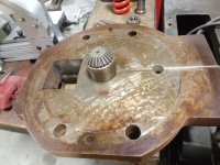
I'm going to clean a bit more rust off the ways before setting the table in place, but once it's on I can get some better measurements and see what material will cost, and might even get a quote for an off-the-shelf rack for reference (or something to budget for if it gets down to it:ack2:). I plan to make the thickness a little undersized and shim the rack to the correct height. Before I put the table on, I also want to flip it over and get a matrix drawn up of all the mounting holes.
 
Last edited:

M.B. Naegle

Titanium
Joined
Feb 7, 2011
Location
Conroe, TX USA
There's still a lot of rust to clean off the ways before they'll be slick and safe enough for the table to slide on, but I went ahead and set the table back in place. I was pleasantly surprised that the gear rack only needs to be about 1 3/8" thick. It could be was narrow as 4 3/8" or as wide as 6", but the grime on the pinion seems to indicate 5" wide. The pinion has almost no wear. I think Tyron is right though that I'll need to be careful cutting the new rack sections so they don't warp. I think a good approach would be to rough cut the teeth, then inspect and straighten the bars in a press, then inspect and straighten again after cutting the final pass. If they'll be short enough, I can also stress relieve them in our oven between straightenings. (The 53' Chevy in the background is my daily driver. I snapped these pics before coming home)
20220716_101407.jpg
20220716_101249.jpg
20220716_101321.jpg
The ways however look to have a fair amount of wear. Nothing deep though and it looks even across the whole ways, but there's no scraping visible anymore and there's lines and shallow ridges that keep the rust from scraping off. The chemical rust removal has had good results, but I'll likely do some wire buffing too as it's got nothing to damage. Rescrapping the ways won't be nessisary right now though. First I'll get them clean and oily and get some work out of the machine. A complete restoration is something I'll likely do with my boys when they're older.
20220716_101500.jpg
There are also quite a few casting defects in the ways and some other machined surfaces that look like they were filled with lead. It's a good case study for how durable of a repair it is.
20220716_101336.jpg
Had some much appreciated rain yesterday, but you can see that the table tool trays have nowhere for it to go, so like the way oil boxes, I'll drill a couple drains in them that can be threaded and plugged later once there's a roof over everything.
20220716_101349.jpg
Other missing pieces include the table trip assemblies (likely tossed with the table rack). The t-slot plates are there and I'm sure I can come up with a suitable replacement, but I wonder if it had the one-touch clamping trips that the 1920's catalogs reference? It sounds like easy but ridged locking mechanisms was something Whitcomb liked to apply, as they did it with the plainers columns, and the tail stock on my Whitcomb Blaisdell lathe.
 
Last edited:

M.B. Naegle

Titanium
Joined
Feb 7, 2011
Location
Conroe, TX USA
If the bed/base had provision for bolting down to the concrete the wear on the ways wouldn’t be too much of an issue. You could usually “ bend the bed straight “ just as long as it wasn’t too far out.

Regards Tyrone.
There's a bolt hole inside each far corner of the base. The box shape of the base is divided all down the middle and there are no feet or pads, so it's like two long bars sitting on the floor.

Do plainer beds typically need periodic releveling or adjustment like a lathe bed, or with a solid foundation should it be fairly permanent? After it's on the foundation, I'm trying to decide if it should be mechanically leveled with screws or shims, or more permanent with mortar.
 

Jim Christie

Titanium
Joined
Mar 14, 2007
Location
L'Orignal, Ontario Canada
Nice to see that you are making some progress with your planer.
I was thinking maybe there are some applications for racks and pinions that may be available from some surplus machines at scrap value instead of trying to make one.
If you are lucky you might even find some to match your pinion .
You could splice together shorter lengths or add spacers or mill down to give the correct height to mesh with the pinion ,
One place I looked mentioned racks for sliding gates and for tower and overhead cranes.
Maybe someone else will suggest some other applications where they may be found.
Jim
 
Joined
Apr 19, 2006
Location
Manchester, England
There's a bolt hole inside each far corner of the base. The box shape of the base is divided all down the middle and there are no feet or pads, so it's like two long bars sitting on the floor.

Do plainer beds typically need periodic releveling or adjustment like a lathe bed, or with a solid foundation should it be fairly permanent? After it's on the foundation, I'm trying to decide if it should be mechanically leveled with screws or shims, or more permanent with mortar.
If the foundation have been done to a reasonable spec they don’t need re-levelling too often. Especially a small one like yours. I had one customer that had a large planer-mill that had been positioned quite near a river bank. From what I was told they’d skimped on the foundation when it was installed. I was re-levelling that pretty often ( once a year ). Eventually they bit the bullet, took my advice,and brought in a specialist company in to pump concrete in under the foundations.
That one was a ball ache. It had a system of wedge mounts under the bed but in and around the column area when you screwed the wedges in they just buried themselves into the concrete and the machine stayed more or less still.
I had shim it up about every 2 ft around the bed. Undo the holding down bolts in the area. Bang in a huge wedge with the sledge hammer, put in your pile of shims, knock out the wedge, tighten the holding down bolts, check the level. Oh shit, too high. Bang in the wedge again etc etc.
A really tiring job. The whole machine weighed about 90 tons ( 180’000 lbs ? ). Good job I was relatively young.
I wouldn’t grout the machine in. If you think the gap between the machine and the ground is un-sightly tap in some pieces of timber that you can remove if need be.

Regards Tyrone.
 
Last edited:
Joined
Apr 19, 2006
Location
Manchester, England
HGR had a couple of planer tables listed. One did show a gear rack still mounted on the underneath side of the table. Shot in the dark, if they are willing to part with the gear rack.
A lot will depend on how old the tables are. The old tables had straight toothed racks but the more modern machines usually had a spiral drive with a helical rack. Worth a phone call though.

Regards Tyrone.
 
Last edited:

M.B. Naegle

Titanium
Joined
Feb 7, 2011
Location
Conroe, TX USA
I'll have to do some looking if there’s any place in Houston that might part out old cranes. So far my online searches have only turned up new gear rack stock, and it looks like it would cost anywhere from $800 to $2000 for a 4 foot section.
 

M.B. Naegle

Titanium
Joined
Feb 7, 2011
Location
Conroe, TX USA
20220810_182426.jpg
Havn't made a lot of progress on this project lately, but here and there I've been squeezing little bites in (how you eat an elephant and all). Since the left work head was already apart, I've been putting it through the evaporust bucket a piece at a time before putting it back together. The back of it still shows original scraping. Found some fasteners missing and have been making replacements as I can, such as these 3/4" bolts made from 1 3/8 hex stock, which seems to be the common set-up bolt head size.
20220810_183755.jpg
Once the head is back in one piece, it'll go in storage until the planer has a roof over it again. The adjusting screws iron acme nut is pretty well stripped, but not all the way, so I took dimensions from it and will make another before or when it fails.

I noticed that none of the adjusting screws or sliding ways on this machine have any kind of incremental dials or rules, with the exception of the work heads having degrees on the side to set tilt. Is this just how old planers were, or just planers in general? Would everything just have been set with surface gages, planer gages, and shim stock (considering this was before indicators became common)?


Top