What's new
What's new

New Featherweight Angle Plate in the Drawing Stage. Metrology and Setup Versions to be Made

eKretz

Diamond; Mod Squad
Joined
Mar 27, 2005
Location
Northwest Indiana, USA
The thermal expansion should not change the angle unless the temperature of the part is uneven. This is why inspection gear is either always kept in a temperature controlled room or allowed to equalize in temperature for a long period of time before used in a very critical application.
 

dgfoster

Diamond
Joined
Jun 14, 2008
Location
Bellingham, WA
OK, I could not stand it. I decided to see how bare-hand hand contact with a 1.25 dia by 10" long steel bar might affect length. I did the test with a bar that was at thermal equilibrium with the 58 environment of my shop.

Forrest Addy outlined the following methodology which was simpler to execute than what I had in mind. I simply chucked it up in the bar in the headstock of my EE and placed 2-4-6 and 1-2-3 blocks on the saddle to align my Federal gage with the free end of the bar. I used the tailstock to "block in" the gage. I zeroed the gage and then with my bard hand firmly gripped the bar in its mid- section and kept an eye on the bar. I was surprised to see that the gage didn't flicker up a tenth for 100 seconds. Then I took my hand off and within a few seconds it cooled enough to read .0000"

So, I think the take-home is that brief casual contact with the strut will not deflect the plate to a commonly measurable extent. I probably still would insulate the strut if I were really trying to do fussy work. But, for most day-to-day use just being aware of making brief contact would do.

Here are pics of my setup:
Testing Thermal Expansion3.JPGTesting Thermal Expansion2.JPGTesting Thermal Expansion.JPG

Comment: I expected a much shorter period of time prior to registering .0001" deflection.

[Side note: The design of a garden-variety camelback straight edge would tend to amplify distortion of the sole of the SE due to unprotected contact with the bow and I would think the SE would be more sensitive to hand contact due to its design and due to the smaller mass of the bow compared to the strut above.]

Denis
 

SIP6A

Titanium
Joined
May 29, 2003
Location
Temperance, Michigan
Why are you using a core for the web? As drawn your going to have a sharp corners where it meets the two legs of the angle plate, that's just asking it to crack when it cools. If you need to have your name on it you could make the lettering stand proud of the surface and the piece with the lettering would be the core.
 

dgfoster

Diamond
Joined
Jun 14, 2008
Location
Bellingham, WA
Why are you using a core for the web? As drawn your going to have a sharp corners where it meets the two legs of the angle plate, that's just asking it to crack when it cools. If you need to have your name on it you could make the lettering stand proud of the surface and the piece with the lettering would be the core.
I hear your concern, Sipa6A. However I think that cracking is extremely unlikely there. I suspect you are thinking of this through the lens of quenching tool steel. And cracking would be an immediate concern. But iron seems much more forgiving than toolsteel. And I am not quenching it but rather allowing it to very slowly cool which probably helps. Whatever the factors, in the several hundred castings I’ve made I’ve yet to have one crack. I hope that record continues but you never know. Each time I do a new casting pattern it seems to teach me some new lessons.

Added: above I did not respond to the question as to why I chose to insert the letters rather than make them stand proud which would have been much easier. Making them stamp proud would still require use of a loose piece which is very similar to using a core. But the main motivation was aesthetics and hand feel. I didn’t want the pointy little bits of letters to be under a persons hand when they grip the brace although that certainly wouldn’t be very objectionable I know. And which is obviously just a personal preference but But the main motivation was aesthetics and hand feel. I didn’t want the pointy little bits of letters to be under a persons hand when they grip the brace although that certainly wouldn’t be very objectionable I know. And secondly, I just think it’s looks better to have them inset which is obviously just a personal preference but that’s what it is.

Thanks for your comments.

Denis
 
Last edited:

dgfoster

Diamond
Joined
Jun 14, 2008
Location
Bellingham, WA
And what lessons does it have to teach me? I just poured it along with some 8” prisms. A couple mins after the pour---still smoking. FIrst Casting of half model.JPG
 
Last edited:

dgfoster

Diamond
Joined
Jun 14, 2008
Location
Bellingham, WA
And shaken out of the sandHalf Model Shaen Out of Sand.JPG
Unfortunatley in trying to hurry the care along by microwaving it, I managed to fuse it to the core box. So, I had to break it free and there was not time to make a new one. (We are to have a persistently-subfreezing cold snap here beginning tomorrow. Greensand work in my unheated barn does not work well at 20deg F.)Defective core base rendered.JPG

The core did its jobv just fine and wouyld have looked good had I not botched the core.

However, I am quite pleased that there were no shrink defects or significant voids. Had I used a wash on the mold (no time this go round) there would have been a cleaner rendition as well. I am encouraged, though that the mold will work jsut fine if properly managed and if a good core is made. My replacement part for the resin printer is supposed to come Wednesday. Once we thaw out, I'll make a more concerted and less hurried try for a good casting. not just proof of concept.

Here is a ten-second video of the partially fettled casting:

Overview of casting

Denis
 

Attachments

  • Defective core base rendered.JPG
    Defective core base rendered.JPG
    265 KB · Views: 8

dgfoster

Diamond
Joined
Jun 14, 2008
Location
Bellingham, WA
I’ve been working on the full-size pattern more and got some more data concerning the strut and likely temperature distortion of the plate due to hand contact with the strut. See the linear distortion thread I recently posted information on.

I did get my new resin printer, finally. So I can move ahead on the core box for the lettering on the strut.

Denis
 

dgfoster

Diamond
Joined
Jun 14, 2008
Location
Bellingham, WA
While making os expansion observations as detailed in a parallel thread I have also been making some progress on the match plate for the metrology angle plate casting that should be cast next week---assuming the weather really does get out of the low teens and the 12" of snow melts.

Making the match plate for the pattern has been the crucial step and one that I approach with caution as screwing up a pattern that has been filled, sanded, filed and painted to as close as possible to perfection would make for a really crappy day.

The key is to make registration holes in the pattern that allow mirror images of the pattern to be in very close register on the top and bottom of the match plate. to establish registration I used 1/8" dowels carefully located in each half of the pattern with corresponding through holes made in the plate. (I use 3/4" sign board plywood for the plate as it is made to high standards and has a hard smooth face. It is not cheap, but it is worth it.)

Here are a few pics:

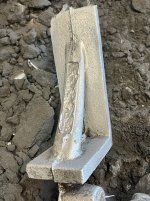
The holes in the pattern pieces and in the plate are made with the mill so that they can be accurately located. I predrill the holes and finish them to size and straightness with an end mill. You can see a large squatty pin in the mid upper portion of the first pic. It is a registration pin for the cope portion of the flask. The flask halves must register accurately with the plate and, after packing with sand, have to register just as accurately with each other. So, a strategy similar to the one used to register the pattern pieces permanently to the plate is used to temporarily register the flask to the plate as it is packed.
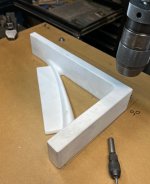
Drilling dowel holes.JPGDrilling dowel holes  predrilled and then milled.JPG

Whoa! They fit.
Drilling dowel holes They match.JPG

Here is a bit more detail on the flask registration pins.Flask registration pins.JPGFlask registration pins2.JPG

The flask sides and the plate are through bored precisely on 14" centers and pins and sockets permanently fixed in the holes so that the flask-plate-flask assembly is in good registration and then the flask-flask assembly is in good registration.

I have also got the core box almost done. More on that later.

This afternoon I'll be gluing the pattern pieces to the plate and making a micro fillet at the junction of the pattern pieces to the plate. Slow, fiddly work.

Denis
 

Attachments

  • Drilling dowel holes They match.JPG
    Drilling dowel holes They match.JPG
    108.5 KB · Views: 1


Top