May I ask the purpose of the original disassembly? Was there a problem with the machine, or did you just want to do a thorough cleaning and inspection?
-It was very much a "snowball" situation.

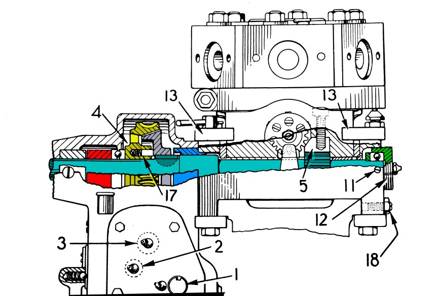
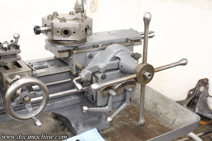
My machine has an "automatic" collet closer/bar feeder arrangement. It's run by an electric motor, but the motor has been long gone. Previous owners used a manual-bypass lever that's really only intended to use while setting up a run for the first time- it works, but they eventually badly wallowed out the hole in the yoke casting.
I wanted to fix that properly- that is, set up something that's a lot closer to a proper collet closer- but that was going to require opening up the whole left-end mechanism, which, really, needed to be cleaned out of chips and swarf anyway.
When I pulled that off, I found the main casting was badly cracked- and had been rewelded, which also cracked. That forced me to strip the paint, grind/weld, etc. and then repaint.
Under the collet/bar-feed, of course, is the gear drive for the feed rod. This, too, was chock full of old grease with embedded chips and junk, so I wanted to clean that off, too. After painting the castings for it, I decided I'd go after the dry, flaking paint on the main headstock... and it all snowballed from there.
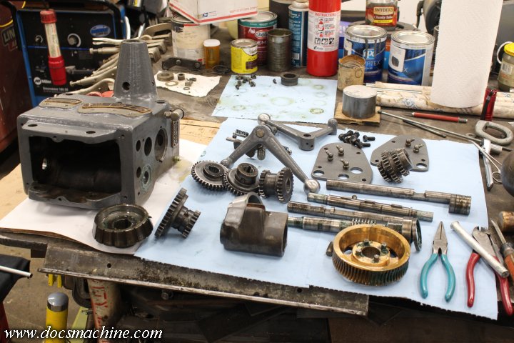
The fact is, the gearbox worked fine, near as I could tell. If I'd had a jet-wash machine or a hot-tank I could have dropped the thing into, intact, to clean it out, I would have. But it was the last dirty piece on a machine that was otherwise now clean and freshly lubed, so I figured I'd pull it apart, give it a thorough cleaning, paint it, etc.
Overall, I'm glad I went through the effort. There were plenty of places where just running it as-is would have eventually caused damage due to the swarf-filled grease, packed dirt in the gear teeth, etc.
Also, did you need to replace any of the parts? And if so, were you able to purchase them, or did you have to machine your own parts?
-In the overall rebuild, or just the gearbox?
Actually, the answer is basically no for either one. Basically, almost every factory part was still pretty cherry, or at least usable. I replaced the oil pump drive belt (as per my
now-closed overall build thread, that I'm considering reopening if Thermite will keep his fat-fuck face out of it) because the original was a badly-spliced replacement that I felt was too loose.
The only other things I've replaced have been the occasional bolt or setscrew.
The only actual
repairs I've had to do was the aforementioned welding of the closer chassis, and making a repair insert for the gearbox casting I stupidly broke.
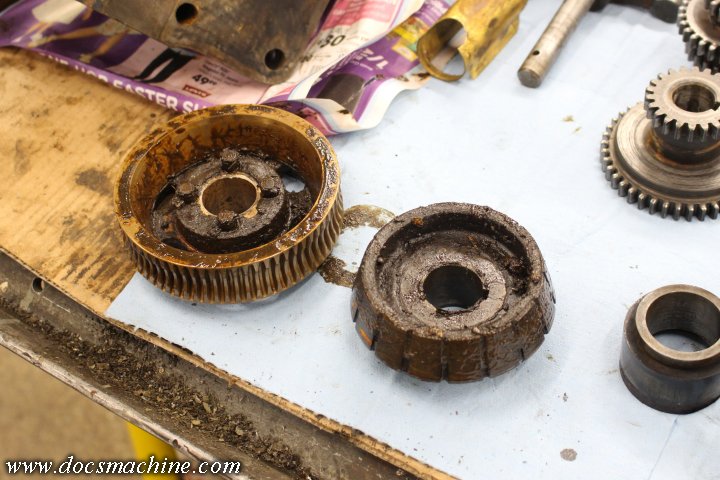
I'm guessing that the large brass worm gear that drives the power feed is the most vulnerable to wear. I'm assuming that's the pinion right behind it in the photo.
-You're correct in that's the pinion, but the fact is, both worm and gear are cherry. I won't say "zero" wear, but if you'd shown them to me cold and asked ho much use they'd had, I'd have said "minimal".
If they're original- and of course there's no way to prove they are- they're in fantastic shape. There's virtually no wear to the hardened steel (and polished) worm, and barely-noticeable wear to the gear.
I have no doubts that with proper lube and care, those parts will long outlast me.
Is that the clutch? Does it just ride against the coned surface of the brass worm gear? No clutch pads or anything like that?
-That's correct. It's a cast iron cone inside a presumably-bronze gear. There are no replaceable pads, and both surfaces are cherry. There's no grooving, no scoring, no nothing.
When properly used and set, it's well-lubed with oil, and when disengaged the two coned surfaces don't contact each other.
If anything on this machine might have indicated a later refurbishment, it's that clutch. But even if the machine were refurbished at some point- no way to tell- it still got
extensive use after that, judging by the massive amounts of dirty, swarf-filled grease I scraped out of every nook and cranny.
So all I can say is don't worry about the clutch. Make sure it's set and lubed according to the manual, and chances are, it'll outlast both of us.
Doc.
")
")
