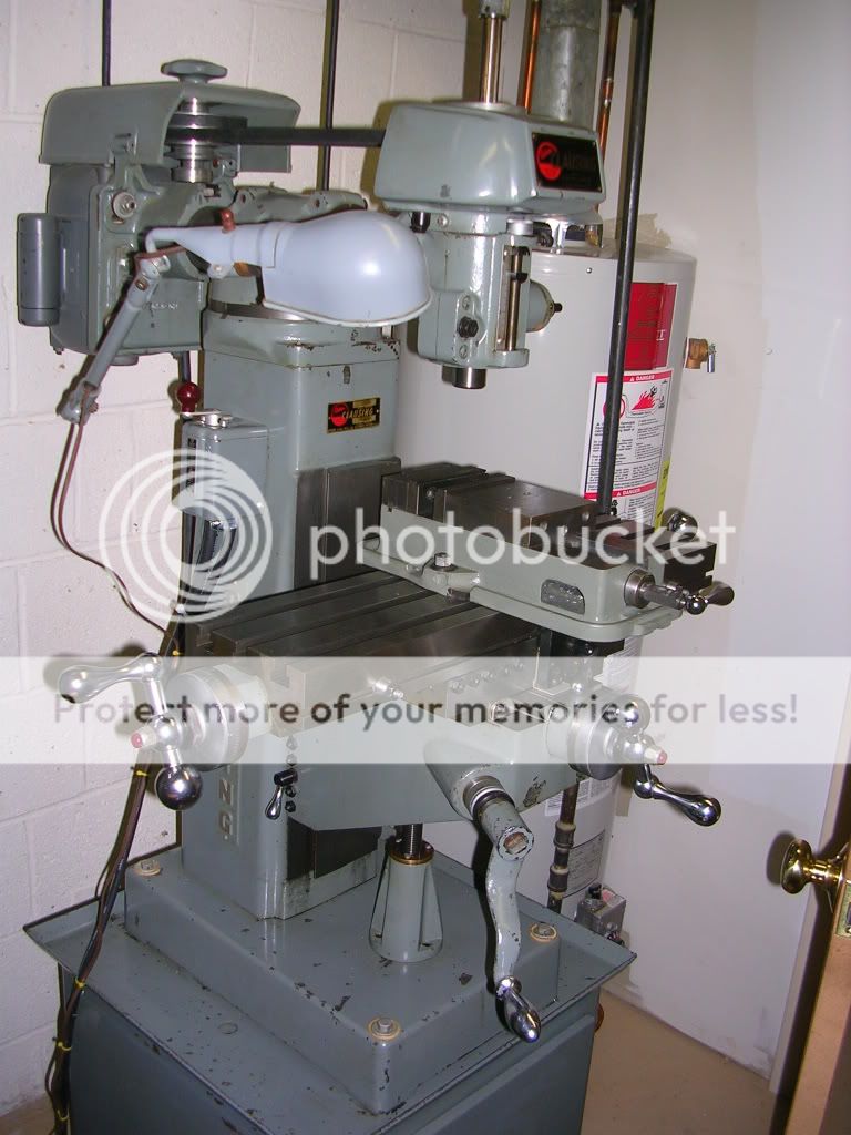
Paula, how did you make the (improved drawbar) mod. to your sx3 mill?
Hi Cliff,
It's pretty simple. I made the shank from 3/4" hex 4140 steel (McMaster #6607K471), and the stem from 7/16-20 B7 alloy threaded rod (Mcmaster #92580A110). Though not hardened, these materials are quite tough, and seem to hold up well for occasional, hobby-type use. Also, when the business end of the threaded rod wears out, replacement is easy.
I didn't make a drawing, but here's a picture of the drawbar assembly (click for a larger view), along with the inexpensive wrench/hammer I use with it (available from Enco, MSC, etc.):
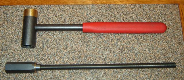
The threaded rod is simply Loc-Tited into a blind 7/16-20 tapped hole in the shank. Adjust the length of the threaded rod to suit. For reference, mine is exactly 10-19/32" long from the end to the thrust washer face. I made mine a bit longer than standard, to get more thread engagement for slower wear of the threads. Be sure to check the length with all your R8 accessories to make sure the threads don't bottom out. The 3/4" hex shank is about 3-5/8" long overall, including a turned pilot to fit the inside of the mill's spindle.
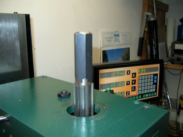
Since I already had one, I added an oilite washer (press fit) to the shank, to help prevent galling where the shank bears against the top of the spindle. I also recommend applying an extreme pressure lubricant, such as Anti-Seize, to the lower end of the threaded rod, as well as the thrust surface at the top of the spindle. Here's a view of the drawbar in place, with the "guard" removed:
I decided to take the idea a step further, and added a spindle-lock to the mill as well. This eliminates the need for fumbling around with that goofy spanner wrench on the face of the spindle. With this setup, when I want to change tools, I just grab the wrench/hammer thingie, and go to it.
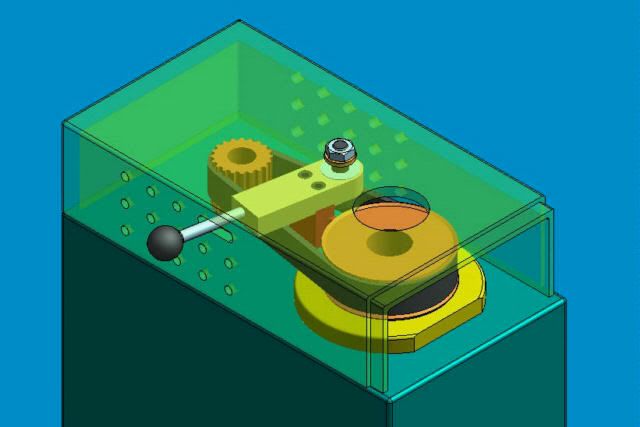
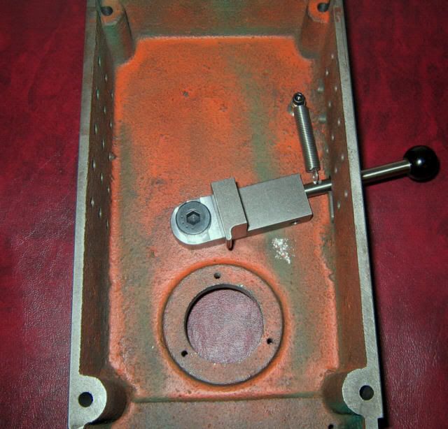
The spindle lock consists of a spring-returned lever, pivoting on a shoulder bolt, with a small "tooth" that engages a corresponding groove in the spindle pulley. Pulling forward on the lever engages the tooth, locking the spindle while the drawbar is loosened or tightened. When released, the lever returns to the disengaged position. Here's a 3D CAD view of the installed spindle lock mechanism:
And here is a view inside the belt cover, showing the actual assembled parts:
I do have drawings for the spindle lock, in case you're interested in making one for yourself.
Paula





 )
)  . At 75 bux v. the 550 some one is asking for that rusnok head.....