What's new
What's new

10EE KB 255D drive problems; Parker 514/507 conversion questions

Cal Haines

Diamond
Joined
Sep 19, 2002
Location
Tucson, AZ
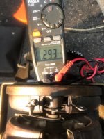
196 Ohms makes more sense than 1400 Ohms, but it's still not right. You should see about 400 Ohms at one end.

Hook your VOM up to the two terminals and watch the reading as you slowly rotate the wiper from one end to the other. At one end you should read 0 Ohms (or very close). You should read 0 Ohms from that end until the wiper reaches the middle of its travel (12 O'clock position). From there, the reading should climb slowly and evenly until you hit a maximum value of about 400 Ohms. At no point should the meter read open. Please do that test and let me know what you observe.

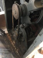
There should be a number stenciled on the body of the rheostat, what is it? Please post photos of both sides of the rheostat pair. Also, please post a photo of the tailstock end of the motor/generator.

You do appear to have most of an MLSR setup. That's not very common and the relatively few MLSR setups that were made generally got taken out of service. It wasn't a very good system. It allowed the operator or the movement of the carriage to knock the headstock threading clutch out of mesh and was pretty hard on the machine; Monarch quickly discontinued it.
 

DAN Z

Aluminum
Joined
Mar 18, 2005
Location
RI
This is what was on the side of the Rheostat in red nothing on the other side. Also at about 3/4 around the dial the the reading dropped off. It reads 0L. Sounds like I have a bad rheostat. My lathe is back up against a wall, this is about the best I can do on getting you a picture of the motor/generator.
 

Attachments

  • IMG-9482.JPG
    IMG-9482.JPG
    313.6 KB · Views: 6
  • IMG-9452.JPG
    IMG-9452.JPG
    262.3 KB · Views: 5

DAN Z

Aluminum
Joined
Mar 18, 2005
Location
RI
That is the right hand rheostat. I'm not sure when the resistance starts to climb, I can check it tonight, but I can tell you when I turn the knob to increase the spindle speed it takes a few full turns of the know before the rpm starts to pick up.
 

DAN Z

Aluminum
Joined
Mar 18, 2005
Location
RI
I check it again this morning. The reading are all over the map, I'm going to borrow another meter for a second opinion. The reading are not making sense.
 

DAN Z

Aluminum
Joined
Mar 18, 2005
Location
RI
Update: I borrowed a friends meter got similar readings. See the attached readings. I removed the rheostat for better readings. Please review the photos they are in order. notice the location of the arm. Not sure what we are going after. It seems that my rheostat is bad, but even if it was good, I thought because the KB controller was only putting out 190 vdc I would never get the full strength out of my motor.
 

Attachments

  • 6.JPG
    6.JPG
    124.9 KB · Views: 5
  • 3.JPG
    3.JPG
    130.4 KB · Views: 5
  • 2.JPG
    2.JPG
    97.3 KB · Views: 5
  • 2.5.JPG
    2.5.JPG
    134.2 KB · Views: 5
  • 1.JPG
    1.JPG
    136.9 KB · Views: 5
  • 7.JPG
    7.JPG
    67.7 KB · Views: 5
  • 8.JPG
    8.JPG
    115.5 KB · Views: 5
  • 9.JPG
    9.JPG
    114 KB · Views: 5

rakort

Hot Rolled
Joined
Apr 27, 2011
Location
Central Wisconsin
Well at fist glance, it's looking good to me. For half the rotation you should be reading near 0 ohms. Then during the other half of the rotation it should increase to a much higher level which appears to be what is happening.
 

Cal Haines

Diamond
Joined
Sep 19, 2002
Location
Tucson, AZ
Update: I borrowed a friends meter got similar readings. See the attached readings. I removed the rheostat for better readings. Please review the photos they are in order. notice the location of the arm. Not sure what we are going after. It seems that my rheostat is bad, but even if it was good, I thought because the KB controller was only putting out 190 vdc I would never get the full strength out of my motor.
Based on the marking on the rheostat and your resistance measurements, it looks like you have the wrong rheostat. Your motor seems to be one with 115 VDC field windings, which is paired with a 400 Ohm rheostat for proper field weakening. Your rheostat appears to be the 1600 Ohm (nominal) rheostat that pairs with a motor that has 230 VDC field windings.

It is true that your KB controller will not provide the performance of the original drive system. However, very few of use need, or make us of, the full power of the motor. There are people here running KB drives and the performance of the lathe meets their needs. On the other hand, there are people that are more concerned with specs than actual usefulness.

First, let's talk about how a Reliance DC motor works: The motor operates in two modes, the first is "base speed mode". In that mode, full voltage (115 VDC) is applied to the field and the armature voltage is varied from 0 to 230 VDC, resulting in the motor running at speeds from near zero to 690 RPM. (Spindle speed depends on the pulleys that are installed.) The second operating mode is "field weakening mode". In field weakening mode, the armature voltage is held at maximum voltage (230 VDC) and the field voltage is reduced (weakened), reducing the back EMF in the winding, and allowing the motor to speed up. As the field is reduced from 115 VDC to about 40 VDC, the motor will speed up from 690 RPM to 2400 RPM with no loss of power.

There's no reason that a KB drive can't provide good performance--equivalent to that of the original drive--over most of the base speed range. Since the drive can't provide 230 VDC to the armature, the motor isn't expected to reach 690 RPM at full field. However, weakening the field with the armature at 190 VDC will increase the motor speed. At that point you won't have as much torque available as the original drive, but that may not be a problem, depending on your application. And I don't know that you can expect to get the motor up to 2400 RPM, but again, that might not be a problem, depending on your actual needs. (I have an original MG drive and a 4000 RPM spindle, but I've never run the spindle above 1200 RPM.)

In post #15 you reported that you were able to reach 850 RPM (at the spindle) with armature and field at maximum. (That's higher than I expected, but you also have 131 VDC on the field.) What I don't understand is why you can't get the field voltage down enough to give you higher speeds than you are observing. With 1200+ Ohms in series with the field, you should be over weakening the field. (Which is not a good thing.)

I think that we've established that you have the wrong rheostat. But as long as you're OK with having to individually adjust the armature and field voltages (that is, using two knobs, instead of the original single-knob control), there are several other ways to provide field voltage control. One is to use a variable transformer and bridge rectifier to power the field. There are also a number of SCR-based motor controllers, available for under $20, that can be used in a similar fashion.

Unless you're bound and determined to ditch the KB drive in favor of a Parker drive, I encourage you stick with the KB drive long enough to solve the field problem and see if it's sufficient to your needs.
 

rakort

Hot Rolled
Joined
Apr 27, 2011
Location
Central Wisconsin
Here is my normal terse response.

I concur about rheostat measurements....seeing as I have both the 115 / 230 VDC varieties under my roof. I did find my notes on the 230 VDC variety that I believe Cal asked for earlier....as well as the 115 VDC variety. See graph below....230 VDC is expected to be around ~1600 ohms max resistance where as 115VDC is expected to be around half that maybe ~700 ohms.

Yours being a piggy back exciter like Cal suggested it should be a 115VDC exciter...therefore wrong rheostat.

Puzzled as well why the higher resistance reho doesn't lower the field voltage more and allow higher motor/spindle speeds.

Something must be amiss in the wiring?


230VDC Stat.JPG
 

Attachments

  • 115VDC Stat.JPG
    115VDC Stat.JPG
    25.1 KB · Views: 1

Cal Haines

Diamond
Joined
Sep 19, 2002
Location
Tucson, AZ
...
....230 VDC is expected to be around ~1600 ohms max resistance where as 115VDC is expected to be around half that maybe ~700 ohms.
...
There's a factor of four difference in resistance, not a factor of two. To keep the field power the same when you double the voltage, you need to cut the current in half. That means a 400 Ohm series resistor for 115 VDC, vs. a 1600 Ohm resistor for 230 VDC.
 

rakort

Hot Rolled
Joined
Apr 27, 2011
Location
Central Wisconsin
Yeah, not sure what these DC motors are looking for in their fields whether that would be power or current. Certainly two different things. I was thinking more along the lines of current. P=V*I, P=I^2*R, V=I*R, etc etc

My 115VDC stat measures E1-F2 400 ohms max (so you are right as I look at the schematic for the field) and the other side of the stat (E2-GF2) maxes at ~ 700 ohms on the 115 VDC stat.
 

DAN Z

Aluminum
Joined
Mar 18, 2005
Location
RI
Can I add an 1200 resistor in series to bring ,my Rheostat in line with what you are saying, or does anyone have a 400 ohm rheostat to sell?
 

rakort

Hot Rolled
Joined
Apr 27, 2011
Location
Central Wisconsin
No it's not going to work that way. You would be closer to add a resistor in parallel. Need to study DC circuits and resistors.

Need to look for the proper rheostat and resolve why the existing one doesn't overspeed the motor with its higher resistance
 

Cal Haines

Diamond
Joined
Sep 19, 2002
Location
Tucson, AZ
Finding a 400 Ohm rheostat is not going to be easy. Looking on eBay, you'll see that 500 watt Ohmite rheostats go for over $100. The variable transformer method makes more sense for the money. Plus, the way the things work, some can actually boost the output voltage to the rectifier so that you get a good, honest 115 VDC out of the rectifier (instead of the usual 90 VDC). The down side is that most need 120 VAC input. $20 SCR motor controllers are available that will work from 240 VAC and (with a bridge rectifier) put out 40 to 115 VDC.

Thing one is to decide if you want to continue down the KB drive road. We can do a couple of tests to see what the drive can do for you, properly configured, so that you can better decide.
 

Cal Haines

Diamond
Joined
Sep 19, 2002
Location
Tucson, AZ
Basically, disconnect the rheostat and do some machining operations to see how it performs at or below base speed. Then, adjust the rheostat to 400 Ohms, hook it back up and see if the field voltage is correct for proper field weakening (look for about 40 VDC). If not, there are several things that be done to get proper voltage to the field. Once the field is properly weakened, do some high speed turning operations to check performance at whatever the maximum speed turns out to be.

I think it would be best, at this point, for us to talk on the phone, so that I can better understand where you're at and what your goals are. I'll send you a private message.


Top