Largest Manufacturing Technology Community on the Web
Stay Connected:
You are using an out of date browser. It may not display this or other websites correctly.
You should upgrade or use an alternative browser.
You should upgrade or use an alternative browser.
10EE KB 255D drive problems; Parker 514/507 conversion questions
- Thread starter DAN Z
- Start date
- Replies 56
- Views 1,556
Hobby Racer
Aluminum
- Joined
- Apr 18, 2015
They are NOT the same.I will let you know. Are both of the rheostat's the same?
Cal Haines
Diamond
- Joined
- Sep 19, 2002
- Location
- Tucson, AZ
Disconnect one of the white wires connected to the rheostat. Turn the speed control knob to maximum and read the resistance. With the speed control knob set to minimum you should read close to zero resistance. You should see zero resistance for the lower half of the speed control range, then the resistance should start to climb smoothly until you reach the maximum value.
rakort
Hot Rolled
- Joined
- Apr 27, 2011
- Location
- Central Wisconsin
agreed the two resistors have an "inverse" profile if you will. flat for half the range then gradually change in the other half of the range,Disconnect one of the white wires connected to the rheostat. Turn the speed control knob to maximum and read the resistance. With the speed control knob set to minimum you should read close to zero resistance. You should see zero resistance for the lower half of the speed control range, then the resistance should start to climb smoothly until you reach the maximum value.
Attached is snip from a spreadsheet of some of the info I captured when messing around with RD piggy back and inline exciter drives.
IIRC what is attached refers to the typical piggy back 115VDC exciter arrangement.
Attachments

Peter.
Titanium
- Joined
- Mar 28, 2007
- Location
- England UK
I'd like to know how you achieve that I could only get about 190v from mine. I had to transform the input voltage up to 290v to gt 240vdc out to the motor.I get a measurement of 240VDC (when adjusted properly) out of my 514C with only my 240VAC mains as input to the drive (BTW my mains actually measure out at 245VAC)? I understand there are losses in the AC->DC conversion but since the VAC value is the representation of the equivalent DC power dissipation, shouldn't a full wave rectifier be able to achieve an equivalent DC output close the to input AC value, minus any electrical losses?
In case anyone is interested you can bump the voltage up to the input terminals on the Parker drive to anything you want (up to the drive's limit) but you MUST only put normal supply voltage into the control circuit. There's a handy jumper wire to connect in the correct voltage input.
In testing the resistance on the outer ring. I had a range from 0 to 1.426k Ω
I could not get a reading from the inner ring. It looks like neither one has been cleaned since they were installed in 1942. perhaps, it would not hurt to remove them and clean... Is my reading in spec?
I could not get a reading from the inner ring. It looks like neither one has been cleaned since they were installed in 1942. perhaps, it would not hurt to remove them and clean... Is my reading in spec?
Hobby Racer
Aluminum
- Joined
- Apr 18, 2015
I double checked today with my Fluke meter and I am getting 220VDC at the motor when inputting 245VAC into both the input and control terminals. That is the upper limit when I have the potentiometer P10 (Maximum Speed) set to the max.I'd like to know how you achieve that I could only get about 190v from mine. I had to transform the input voltage up to 290v to gt 240vdc out to the motor.
In case anyone is interested you can bump the voltage up to the input terminals on the Parker drive to anything you want (up to the drive's limit) but you MUST only put normal supply voltage into the control circuit. There's a handy jumper wire to connect in the correct voltage input.
I tested so many variations of input voltages, I got confused on the numbers. But still really good DC output from mains voltage!
BTW: I was getting 240VDC when I had 285VAC input to the drive and P10 turned down a bit.
Cal Haines
Diamond
- Joined
- Sep 19, 2002
- Location
- Tucson, AZ
I don't know what you mean by "inner" and "outer" ring. There are two rheostats, stacked on a common shaft. You have only one connected, the one with the two white wires connected; that's the only one we're interested in. It's the one on the right in the photo that you posted earlier:In testing the resistance on the outer ring. I had a range from 0 to 1.426k Ω
I could not get a reading from the inner ring. It looks like neither one has been cleaned since they were installed in 1942. perhaps, it would not hurt to remove them and clean... Is my reading in spec?
If you have a motor with a 115 VDC field, you should see resistance readings from 0 to about 400 Ohms. If your seeing readings as high as 1,400 Ohms, that sounds like the rheostat for an inline-exciter motor/generator, with 230 VDC field windings. If you have a spindle motor with a 230 Volt field, it's no wonder your motor isn't performing.
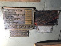
Please post a photo of the data plate on the spindle motor, so we can see what motor you have.
I was not able to find it as of yet. the plate it's not visible. I believe it's the 3HP Reliance large frame DC motor. My reference to inner and outer was the outer, which is what you were asking for is the one on the right. If my resistance is too high, might a good cleaning improve on lowering the resistance.
Cal Haines
Diamond
- Joined
- Sep 19, 2002
- Location
- Tucson, AZ
It's definitely a Reliance 3HP DC motor, but the question is, what field voltage does it need? Motors with 115 VDC and 230 VDC fields look the same. You have an older machine with a T-handle quick-change gearbox; the odds are very good that you have the 230 VDC field version of the motor.
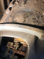
The data plate should be on the top of the motor, just to the left of center and usually at the front edge of the case:

Look in the area marked in red. It might be hiding under a layer of dirt/grease. If not, look for two small holes for the rivets that held the plate. If you find the holes, the plate has been removed for some incomprehensible reason.
Take the cover off of the small terminal box on the right side of the motor and locate the four wires coming from inside the motor. There should be a small terminal strip where the wires are connected:

Disconnect all wires that leave the terminal box to the rheostat or the KB controller (make sure that they are labeled first). Using your Ohmeter, check the following:
The data plate should be on the top of the motor, just to the left of center and usually at the front edge of the case:
Look in the area marked in red. It might be hiding under a layer of dirt/grease. If not, look for two small holes for the rivets that held the plate. If you find the holes, the plate has been removed for some incomprehensible reason.
Take the cover off of the small terminal box on the right side of the motor and locate the four wires coming from inside the motor. There should be a small terminal strip where the wires are connected:
Disconnect all wires that leave the terminal box to the rheostat or the KB controller (make sure that they are labeled first). Using your Ohmeter, check the following:
- Resistance between A1 and A2
- Resistance between F1 and F2
- Resistance between A1 and F1 (should read open)
- Resistance between the case and A1, A2, F1 and F2 (should read open)
rakort
Hot Rolled
- Joined
- Apr 27, 2011
- Location
- Central Wisconsin
I do have resistance curves for the 230VDC rheostat if needed. Pretty sure the one I published earlier was for the 115VDC stat.
Cal Haines
Diamond
- Joined
- Sep 19, 2002
- Location
- Tucson, AZ
Do you have the field winding resistance for a motor with a 230 VDC field handy?
Here is what I got for readings.
Dan
- Resistance between A1 and A2 (2.5Ω)
- Resistance between F1 and F2 (81.1Ω
- Resistance between A1 and F1 (should read open) yes, open
- Resistance between the case and A1, A2, F1 and F2 (should read open) yes open
Dan
Attachments


Cal Haines
Diamond
- Joined
- Sep 19, 2002
- Location
- Tucson, AZ
Sorry. Yes, they look good. I'll get back to you tomorrow with more.
Cal Haines
Diamond
- Joined
- Sep 19, 2002
- Location
- Tucson, AZ
Your serial number and build date puts the machine solidly in the piggyback exciter motor/generator (MG) era; most, if not all, of those MGs, had 115 VDC exciters. The tag on your MG that it's a 115 VDC exciter model. The field resistance of your spindle motor (80 Ohms) is what I expect for a motor with a 115 VDC field. (The field windings on 230 VDC field motors measure about 320 Ohms.) So, everything EXCEPT the motor field rheostat seems to match and is probably original.
Cleaning the rheostat won't reduce the reading that you get between the terminals. The wiper shorts out part of the windings, so if the wiper or coils were so dirty that there was no contact, you would read the resistance of the full winding at all wiper positions; there's no way for a bad wiper-to-coil contact to increase the resistance that you read above that of the full coil. The fact that you were able to get a zero resistance reading means that the wiper is making good contact with the coils.
This leaves us with the mystery of how you're reading 1400 Ohms between the rheostat terminals. The only way to answer that question is to remove the rheostat pair and inspect the rheostat. The body of the rheostat should have the nominal resistance stenciled on it. That mark faces the base casting, so you can't see it with the rheostats in place. The wiper arms should also have a tags riveted to them that give the rheostats' specs. The arms are between the two rheostats and the tags face each other, so again can't read them without taking the rheostat stack apart.
I think that it's worth the time and effort to pull the rheostats. A proper field rheostat will give you better results with the current setup and gives you a good option for field weakening if you go the Parker 514 route. (IIRC, hobbyracer is running that way.)
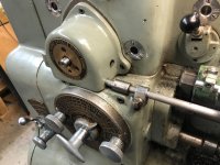
I would like to see photos of the entire machine and a photo of the tailstock end of the exciter. Your machine has the Mechanical LeadScrew Reverse (MLSR) option (which is pretty rare); I would like to see if it's all there.
Cleaning the rheostat won't reduce the reading that you get between the terminals. The wiper shorts out part of the windings, so if the wiper or coils were so dirty that there was no contact, you would read the resistance of the full winding at all wiper positions; there's no way for a bad wiper-to-coil contact to increase the resistance that you read above that of the full coil. The fact that you were able to get a zero resistance reading means that the wiper is making good contact with the coils.
This leaves us with the mystery of how you're reading 1400 Ohms between the rheostat terminals. The only way to answer that question is to remove the rheostat pair and inspect the rheostat. The body of the rheostat should have the nominal resistance stenciled on it. That mark faces the base casting, so you can't see it with the rheostats in place. The wiper arms should also have a tags riveted to them that give the rheostats' specs. The arms are between the two rheostats and the tags face each other, so again can't read them without taking the rheostat stack apart.
I think that it's worth the time and effort to pull the rheostats. A proper field rheostat will give you better results with the current setup and gives you a good option for field weakening if you go the Parker 514 route. (IIRC, hobbyracer is running that way.)
I would like to see photos of the entire machine and a photo of the tailstock end of the exciter. Your machine has the Mechanical LeadScrew Reverse (MLSR) option (which is pretty rare); I would like to see if it's all there.
rakort
Hot Rolled
- Joined
- Apr 27, 2011
- Location
- Central Wisconsin
I do some place! I could not easily find them after a quick search. If the greater good needs them I will keep looking.Do you have the field winding resistance for a motor with a 230 VDC field handy?
Cal Haines
Diamond
- Joined
- Sep 19, 2002
- Location
- Tucson, AZ
I found it, thanks.
johansen
Stainless
- Joined
- Aug 16, 2014
- Location
- silverdale wa
The differences reported between folks reading 180v on a 240vac drive vs something much higher can be explained by the volt meter used.
240vac peak is 340v DC, but the average value is 180volts when rectified ( but not filtered ) to DC.
Anyhow a power factor corrected DC drive designed for 240 mains could send up to 400 volts to the motor, (or more if designed for a voltage boost) but I don't know of any commercially available DC drives that can do that.
If you have a DC drive with big electrolytic capacitors in it, then it is likely capable of sending as much as 340vdc to the motor unless it's configured not to. It will not have an SCR in it but rather igbts or MOSFETs
SCR drives don't have big electrolytic caps. 4 quadrant 3 phase drives will have capacitors to commutate the scrs to achieve 4 quadrant operation, and they will not be large electrolytic DC capacitors on the order of 2200uf 450vdc
As requested here are some pictures of my "MLSR". I believes it is all there except for the pointer knob, yes? I pulled the rheostat out and took a measurement on the bench. This time I came up with a reading of 195.7 Ω. Does this measurement make more sense?
Attachments


Similar threads
- Replies
- 14
- Views
- 666
- Replies
- 14
- Views
- 271
- Replies
- 0
- Views
- 4K
- Replies
- 22
- Views
- 2K