rke[pler
Diamond
- Joined
- Feb 19, 2002
- Location
- Peralta, NM USA
You're going to want the contactor wiring to look like this below:

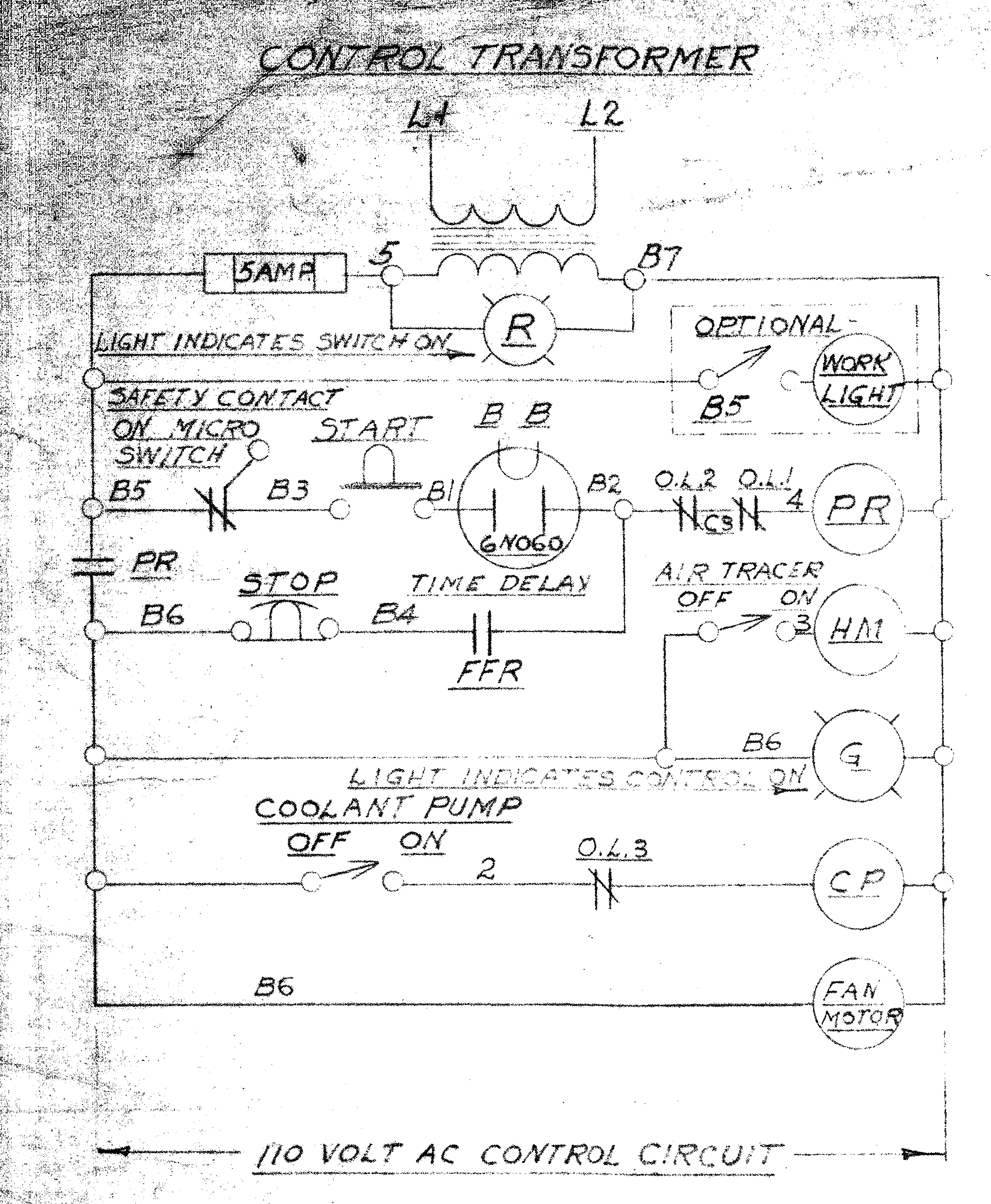
The start/stop is wired to the hold points on the contactor. Start supplies power to the contactor coil, closing the hold point so the contactor stay closed until there's power loss or the stop button is pressed. There are other switches involved (cabinet front and maybe the spindle lock) and overloads but that's the gist of it. You want to find these switches and confirm that they close appropriately and that the Field Failure Relay contacts are good.
Since all that seems to be disconnected on yours either the coil in the contactor is bad (likely) or the wiring from the contactor to the switches got broken (possible, less likely). You need to look for disconnected wires, and to trace those wires from the contactor housing to the switch box. If you can't find them you'll want to add them.
Last edited: