What's new
What's new

Saved a Hendey from the scrappers yesterday

M.B. Naegle

Titanium
Joined
Feb 7, 2011
Location
Conroe, TX USA
All right, I'm still working with the sales-engineer who's quoting the silent chain system, but we have the sizes and dimensions all worked out and it looks like it'll be budget-able.

The new set will be a 3" and 9" (approx.) sprocket and they quoted 1" wide chain for the 5HP application, so that solves the clearance issues.

I'm doing some figuring on the guard now, which I cut out to have a 14" radius on the bottom side and a 10" radius on the top. I'm thinking to keep it simple, I'm just going to flip it around so the big end is on top covering the little motor sprocket, and the small end on the bottom will be plenty big enough for the head-stock sprocket. There's no practical reason to have the extra space up top, but mocking it up on the machine it's aesthetically nice since it matches up with the large diameter of the motor and the overall shape flows well with the head-stock and motor's "round-upon-round" design layout. It's currently 6" wide for the flat pulleys, but I can trim 2" out of the middle easily. I'm going to make a flange to locate and mount around the headstock's input shaft and then add another bracket further up, and I think it will be fairly solid with those two mountings. With these changes the collet tube will work without extensions, so that's another win. It'll still be behind the guard however, so having the extensions might still be helpful to get a better grip on the wheel.

(pictures incoming)

One other challenge is that the sales-engineer noted that these silent chains work best in an oil bath set-up. I'm waiting to hear back if the low RPM and low duty cycle of this lathe will merit manual lubrication (squirt some oil on the chain when you start it up, same as the ways and every other oil point on the machine), but if it really needs a bath, the guard is already welded shut on the edges and I can cut and weld the bottom end to be more of a tub and add some flanges and/or rubber stripping to the clam-shell seams to make it oil tight and add an oil level sight on the side. It wouldn't need to be fully submerged up to the shaft opening, just enough so the chain is pulling oil up with it. They recommended a light weight oil for it so I'm planning on using the same #10 spindle oil that's in the headstock bearings. Of course I'm going to hold making these changes until the sprockets are on the machine.
 

M.B. Naegle

Titanium
Joined
Feb 7, 2011
Location
Conroe, TX USA
I've been distracted from machining in general lately and haven't done much with Ol' Tory. Mainly been absorbed into the service/assembly side of things at work, and after hours I bought an old sail boat to fix up (:wrong::hole:), and am building a tractor shed out back so Goose (1949 Ford 8N) can be out of the way but still out of crack-head sight.

Couple things is that the quote I got back on the silent chain drive ended up being double what I had hoped. Small sprocket and chain are affordable, but the large sprocket is essentially a $700 custom build. I really like the prospect of going with the silent chain system, but need this lathe to pay for itself a bit first, so I'll run the flat belt a little loose for the time being.

On the other hand, I splurged and bought another single wall 16" Hendey apron assembly. Paid a bit more than I wanted, but it was worth it as it'll save me from having to machine all new feed worms and gears, and the Babbitt half nuts are in great shape so I'll shelf that project till it's needed. There are some slight differences between it and my current apron, so rather than swapping the whole assembly I'll likely just use the parts I need out of it and tuck away or sell the rest.
 

ratbldr427

Stainless
Joined
Mar 21, 2006
Location
jacksonville,fl.
A friend offered me a 24" Gisholt turret lathe. The tag called it a "High Speed Brass Lathe".
It had a 3"-4" wide maybe wider(been 45 years ago} silent chain drive. It wasn't in an oil bath as far as I remember. For a hi quality production machine that didn't seem right. Your lathe will never see the service that machine was designed for.
 

maust

Aluminum
Joined
Apr 13, 2008
Location
Lilydale, Victoria/ Australia
Save this planer from the scrapper too, if you can. (It is also in Texas.)
10ft bed, planes 8ft x 30in x 30in. Weighs 12000lbs!!! It is going to the scrap dealer real soon if no one saves it. Maybe you know someone who would want it if you don't. I just hate to see it scrapped.
Note: I have no personal interest in this machine other than hoping it doesn't go to scrap. I don't even live in the U.S.

If the link doesn't work, it is a Whitcomb metal planer on fb marketplace, in Texas

Log into Facebook
 

M.B. Naegle

Titanium
Joined
Feb 7, 2011
Location
Conroe, TX USA
I haven't posted an update in awhile but have made some progress. This is a video from last year I neglected to post.
More recently, I've got the electrical cabinet mounted and wired, with the exception of the spindle controls which are temporarily connected until I get the under bed control done, and I decoded the old Boston VFD so it's working how I want.

Made a little more progress on the saddle too, and my goal is to have it scraped and back on the bed before the end of the year. Pictures and more progress to come.

On a different note, I own a planer now (the old Whitcomb linked above), but it's a long ways from beginning useful. Even still, it's large enough that someday it'll likely get used to fix this ol' Hendey's bed. We'll see if Practical Machinist and this thread is still active when that day comes.
 

M.B. Naegle

Titanium
Joined
Feb 7, 2011
Location
Conroe, TX USA
20220928_200829.jpg
20220928_200802.jpg
20220928_200739.jpg
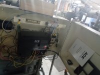
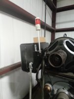
Here's the electrical cabinet. The box is the same one I salvaged from the Czech turret lathe I scrapped, but instead of hanging it off the back of the chip pan, I made a couple brackets and hung it off the back of the motor, which is closer to how Hendey was doing their electrical back In '09, and it's much easier to work with. Inside there's the VFD, terminal blocks, and a contactor for the primary power switch which also allows for safety switches (future plans for a foot switch e-stop). I need to add some fuse holders and tidy up the wires. The red signal lamp indicates if the machine is on, since the spindle speed could be turned down to zero, and I repurpoused an old hour meter to keep track of how much actual use the lathe will see (and adjust the maintenance schedule accordingly), but it doesn't seem to be working so I'll need to find a clock guy that's up to the challenge. As noted before, the forward/stop/reverse and potentiometer controls will go under the front of the chip pan in a large pipe enclosure imitating the old DC potentiometer and tying into the apron control.
 
Last edited:

M.B. Naegle

Titanium
Joined
Feb 7, 2011
Location
Conroe, TX USA
20220928_200409.jpg
20220928_200356.jpg
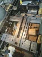
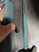
It's hard to see in the shadow, but the chuck side dovetail of the cross slide is making about 50% contact in the back. The gib I surface ground flat and gave it a little scraping to break up the surface. I added a couple oil cups on top of the cross slide, which intersect where the dovetail surfaces meet, and once the chuck side is scraped, I'll carve some oil passages so the oil cups feed the dovetails, which then run into the rulon flat ways underneath.

One other feature I'll need to add is a brass wiper to fill the 1/8" gap between the center of the cross slide and the top of the ways, which will also serve to help direct oil from the oil cups into the grooves carved in the dovetails.
20220928_200434.jpg
20220928_200713.jpg
 

M.B. Naegle

Titanium
Joined
Feb 7, 2011
Location
Conroe, TX USA
20221012_175107.jpg
The shadows and reflection aren't letting me get a good pic of the print, but I reached a stopping point on the cross slide chuck side dovetail. Not perfect, but plenty good.
20221012_180338.jpg
20221012_180847.jpg
Next step was to carve the oil paths on that side.
20221012_181232.jpg
I got the dovetails of the saddle parallel finally. Now I just need to get the point count up on the prints. I made them parallel to the channel for the rear bearing that slides with the taper attachment, as this didn't appear or measure to have much wear (didn't see as much use). I used the chuck side as the primary reference, because when the rear bearing clamps in place, it is clamped against this surface.
20221012_181436.jpg
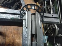
With the chuck side parallel to the channel, I could then mike the two dovetails together. Over 24" It's within .001" parallel. The flat ways are likewise within .001" parallel when miked against the reference surfaces on the bottom of the saddle. I'm happy with that. Now to just get the coverage and point count evened up.
 

texasgeartrain

Titanium
Joined
Feb 23, 2016
Location
Houston, TX
For the cross slide dovetail, I was curious your plan of attack for getting the dovetail parallel to headstock spindle face, or let's say to the chuck face.

Would you adjust the cross slide dovetail, or adjust the entire saddle to get parallel with spindle face ?

And are you intending a very very minor minus reading on a facing cut ? And how much of a minus would your goal be if working toward that ?
 

M.B. Naegle

Titanium
Joined
Feb 7, 2011
Location
Conroe, TX USA
For the cross slide dovetail, I was curious your plan of attack for getting the dovetail parallel to headstock spindle face, or let's say to the chuck face.

Would you adjust the cross slide dovetail, or adjust the entire saddle to get parallel with spindle face ?

And are you intending a very very minor minus reading on a facing cut ? And how much of a minus would your goal be if working toward that ?
The dovetails were not terrible to start with but did have some wear. I mainly needed to doctor them since the flat ways dropped down so far while correcting their wear. To square the dovetails up, I used a dovetail cutter on the mill, followed by a few rounds step scraping until it was close. I also used an old power hack-saw blade to manually undercut the corner between the dovetail and the flat way so that it wouldn't throw things off (I hate scraping into corners). Because I haven't done anything with the bed ways or the underside of the saddle, at this point I'm relying on keeping the saddle as square as it was via the rear bearing channel. I can only measure that feature from the back 1/3 of the ways, but It's the only squareness feature on the saddle that isn't/wasn't worn. If it was out of square, or If I wanted to induce a minus reading, when I refit the underside of the saddle I can selectively scrape the V-ways when fitting them to the bed so that the saddle rests at the desired squareness. I'm estimating that after plaining the bed and underside of the saddle, I'll need to add 1/8"+ of wear material to the bottom of the saddle, so there will be plenty of meat to work with when that time comes. To square it up from the dovetails, I would need to scrape the channel and likely add some wear material to one side to compensate, in addition to scraping the dovetails.

It's a little backwards, but my long term goal still holds to just get the cross slide and the top of the saddle fixed first and fix the bed later. This is due to time/resource constraints, and the bed is still functional. I made the decision to start fixing the cross slide when I realized it was no longer riding on the flat ways, but had worn enough that it was riding on the top flats of the dovetails leaving a gap for swarf to snowball between the flats.

It's been long enough that I'll need to re-measure the saddles squareness between the cross-slide and the spindle to see where it's at, but for my uses my preference would be to make it as close to square as I can, as for any parts I make that need to have a minus reading typically I will relieve the inside of the face.
 

M.B. Naegle

Titanium
Joined
Feb 7, 2011
Location
Conroe, TX USA
One other note for anyone working on a similar project: In the above picture where I'm printing the cross-slide dovetail to a dovetail straight edge, this was easier to do, however I wouldn't recommend it as it was hard to hinge the piece to see if it was rocking, so towards the end I started leaving the cross slide clamped in the vise and held the straight edge to print. The 24" straight edge is my smallest one that's ready to go, but were I to do this again I'd finish and use my 18" straight edge, or buy a 12" one. Hinging the 24" straight edge over the smaller dovetail was tricky, but doable. It started high in the middle since the ends tend to take the most wear (opposite on the saddle dovetails I think, with more wear on the exposed front), so I knew that if I could hinge it and get anything else than high in the middle, it was ok.

Speaking of straight edges, the compound will be one of the next pieces I'll work over... AFTER the saddle and cross slide are back together. The compound ways I don't think are too bad, but the bottom surface that mates to the cross slide needs work. To do the underside I'll need to make a donut surface plate. Luckily I have a perfect casting for this, so one of the first jobs I'll cut on the Hendey when the saddle is back together is getting the casting squared up and ready to scrape. With the compounds smaller ways, I'll definitely finish my 18" straight edge too before I start that leg of the project.
 

M.B. Naegle

Titanium
Joined
Feb 7, 2011
Location
Conroe, TX USA
Did a little on the chuck side of the saddle tonight. A big reason why I procrastinated getting these ways done (in addition to starting more projects :leaving:) is while I had a good grasp of what needed to be done, I wasn't settled on the physical logistics of making it happen. I was trying to find a way to hold the saddle at an angle or something and not have to sling its weight around too much, and finally decided to just leave it flat and scrape upside-down. The Biax wasn't excited about this, so I went back to my old manual scraper, which has proved to be less effort than I thought.
20221013_180627.jpg
20221013_180518.jpg
Hard to get picture with both hands at work, but at my scraping bench I find it easier to kneel for this job and I pull down on the butt of the scraper using the knob as a fulcrum to get the angle and force behind the scrap motion. It's all in the arms as opposed to using your whole body like I'd prefer, but it works well for these narrow surfaces.
20221013_180014.jpg
Good light helps too. Not nessisarily more light though. Some surfaces I get too much glair with a direct light, but for the dovetails I've found that the scraped flat ways reflect just the right amount onto the dovetail.
20221013_180719.jpg
Bluing the straight edge for these surfaces is the same as others. I like using a rubber brayer to spread the ink and the print tells me if I need more or less. A variety of "types" of blue spots is the goal. If they are all heavy and blotchy, too much. If they are all light and thin, to little. I've mostly used canode blue and still have a bit, though now that it isn't available, I'm experimenting with others. I like Stuart's Micrometer Blue. It takes a little more to get a good print, but it dosn't dry out much or change colors if left on the surface overnight, and is easy to clean up. I still have a sealed tube of Dykem to try out, but Stuart's does the job.
20221013_180116.jpg
20221013_180104.jpg
This is where I left it tonight. Still a little low in the bottom middle, but it's getting there.
 
Last edited:

4GSR

Diamond
Joined
Jan 25, 2005
Location
Victoria, Texas, USA
I find it much easier to scrape the dovetails by hand, too. Like your nifty scraper there! The saddles I've reworked in the past 10 years were from 14-15" lathes. I found the adjustable top welding table from HF worked perfectly holding the saddle at an angle to scape the dovetail. The welding table doesn't bounce around too bad. There is a cross brace at the floor you can step on to keep it solid while scraping.
 

marka12161

Hot Rolled
Joined
Dec 23, 2016
Location
Oswego, NY USA
I also used an old power hack-saw blade to manually undercut the corner between the dovetail and the flat way so that it wouldn't throw things off (I hate scraping into corners).
Very timely post. I had the cross slide dovetails on my my saddle ground and the flat ways were milled so my dovetail geometry is pretty good. However since the flat ways were milled rather than ground, i need to scrape in a proper bearing surface. When the shop did the grinding & milling, they did not machine any clearance grooves between the dovetail and flat ways. Connelly recommends doing as you did, adding clearance grooves with a hacksaw blade. Can you elaborate a bit on how difficult (or easy) it was. Are there any specials tricks or traps to be aware of?

Thanks
Mark
 

M.B. Naegle

Titanium
Joined
Feb 7, 2011
Location
Conroe, TX USA
Very timely post. I had the cross slide dovetails on my my saddle ground and the flat ways were milled so my dovetail geometry is pretty good. However since the flat ways were milled rather than ground, i need to scrape in a proper bearing surface. When the shop did the grinding & milling, they did not machine any clearance grooves between the dovetail and flat ways. Connelly recommends doing as you did, adding clearance grooves with a hacksaw blade. Can you elaborate a bit on how difficult (or easy) it was. Are there any specials tricks or traps to be aware of?

Thanks
Mark
I'd make sure you are using a brand new blade (mine are new-old-stock left over from acouple power hack saws the company had years ago). Reason being is every tooth is trying to cut when you slide it through the corner, so rather than trying to bear down into it and "make chips," let the tips do the work so the shavings are more like filings.

It dosn't take much effort otherwise and I just move it with my fingertips. I alternate sliding it flat along the dovetail surface so it cuts into the flat way, and then sliding it flat along the flat way so it cuts into the dovetail. It also helps to slightly file the matting corner off as it dosn't help for it to have a knife edge.

There might be better ways, but it works. Eventually I'd like to make a single toothed undercutting tool that works like a wood plane. Project for another day.
 

M.B. Naegle

Titanium
Joined
Feb 7, 2011
Location
Conroe, TX USA
20221018_185053.jpg
Reached a stopping point on the chuck side.

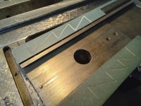
Also carved the rest of the oil lines under the the cross slide, BUT, realized a flaw in my layout. I had wanted the oil to flow from the dovetails down to the flats, but realized that the oil is going to flow out of the undercut between the two surfaces, especially on the gib side as it has a 1/8" gap in that corner. I could fill that gap with some more turcite or make a new gib, but nothings going to bridge that gap good enough to keep the oil from running out. So I'll need to add another pair of oil points for the flat ways. I was hoping to keep the oil holes behind the compound to keep swarf from migrating in, but I might have to just deal with it. The chuck side has a work stop rod running along it that limits where I can poke holes in. Oil running out the undercut will help things however, as any swarf that does get in will be able to flow out.
20221017_193653.jpg
20221017_193719.jpg
20221017_193740.jpg
I plan to add a couple felt and brass wipers to help seal the front and back of the crossslide, and that should cover most of the gap under the gib.
 
Last edited:

M.B. Naegle

Titanium
Joined
Feb 7, 2011
Location
Conroe, TX USA
20221021_181000.jpg
Not as important, but I'm also trying to wrap up a bunch of the little piddly tasks on the lathe, like closing up the paint. The gear train is pretty much done, pending the final fit of the intermediate cover I found on eBay. While doing this, there were a few fasteners and bushings and such that I swapped for better fitting pieces. The big zinc coated washer you see over one gear, for example, was previously a stack of misc. washers.
20221021_181043.jpg
It's getting serious now! Paints on the saddle, although might need to touch it up a little after the last bit of scraping. I'm really pleased with how the t-slot repair turned out. Between the scraping, lead, and paint, you can hardly tell its there.
 

M.B. Naegle

Titanium
Joined
Feb 7, 2011
Location
Conroe, TX USA
Does anyone have any leads/sources for an analog tachometer that I could integrate to this lathe? I don't care how new/old the tech is, wither it's mechanical or electronic, but I'd like to have an old-school needle dial display rather than the new digital readouts that are easy to find. The best candidates I've found on eBay, for example, all go 0 to 1500rpm or much higher. Since this lathe won't use half that, the resolution wouldn't be as helpful as something that goes 0 to 750rpm or thereabouts. A tach would be much more helpful in determining spindle speed given the VFD over geared headstock variables. Without one, I can make a chart with each gear at full speed, but I have to guesstimate the VFD's effect on it.

Short term, I'll likely wire up a digital display, but an old needle dial would look so much more appropriate IMO.


Top