What's new
What's new

New Okuma LS owner with questions

hanneswk

Plastic
Joined
Nov 14, 2020
Location
Lower Saxony, Germany
Some results to show...

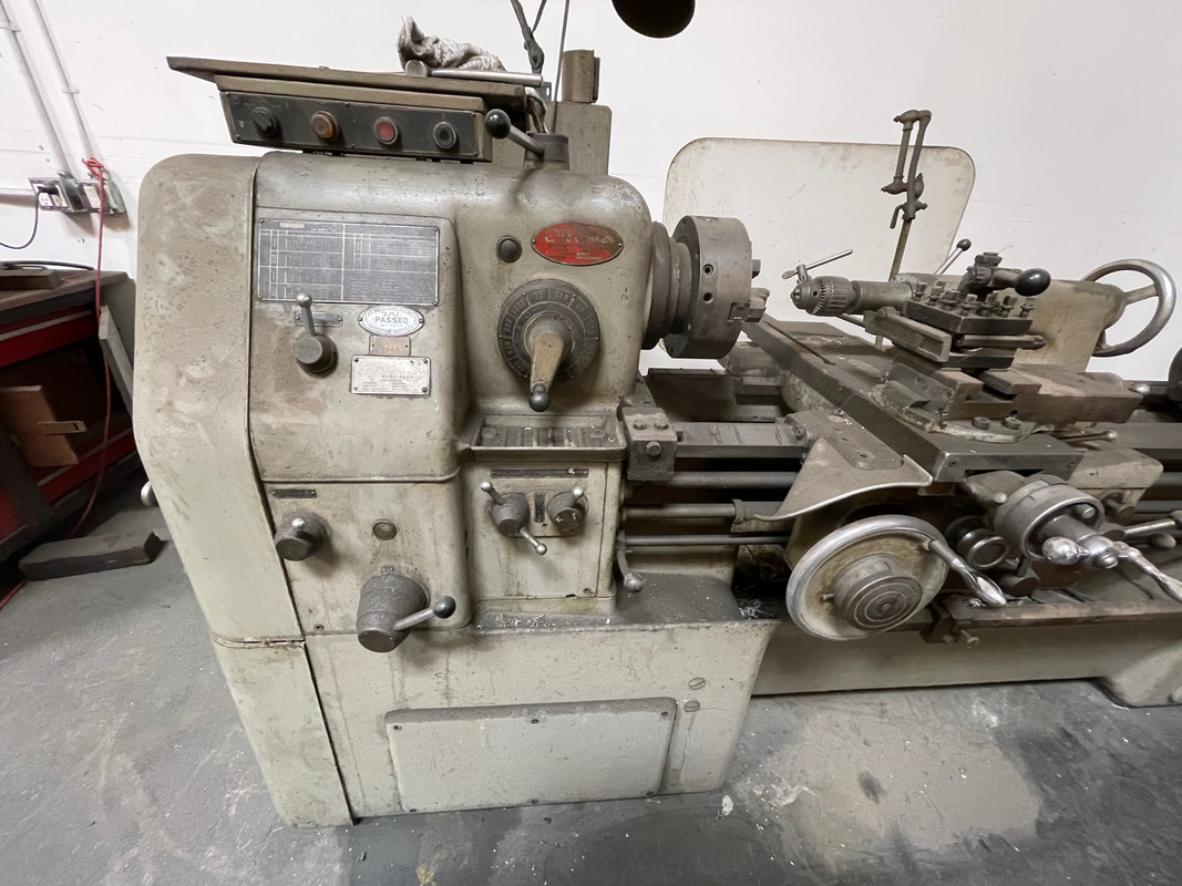
As I started cleaning the apron I noticed that some oil lines were totally messed up. I think chips fell behind the apron and then got wedged between the machine bed and the lines when the saddle was moved back and fourth.
IMG_20201129_172754269.jpgIMG_20201129_172806557.jpgIMG_20201129_172824701.jpg
So I first cleaned the outside and then began to manufacture new oil lines out of copper (OD: 4mm, ID: 3mm).
IMG_20201215_171725698.jpgIMG_20201215_210829254.jpg
 

hanneswk

Plastic
Joined
Nov 14, 2020
Location
Lower Saxony, Germany
Here you can see all the new lines. Later, when I wanted to mount the apron back to the saddle, the oil line on the very left turned out to be in the way for the saddle clamp. I had to modify it quite a bit so that it was at the same level as the line right next to it.
IMG_20201218_220356536.jpg

The front of it looks like this now.
IMG_20201219_102857978.jpg
 

hanneswk

Plastic
Joined
Nov 14, 2020
Location
Lower Saxony, Germany
I went on with cleaning the saddle. It was almost completely clogged with dirt, grime and schmoo. I managed to flush all oil ports with diesel and compreesed air. What came out of the ports looked like this.
IMG_20201219_201504997.jpg

After a few liters of diesel, lots of scrubbing and even more liters of brake cleaner the saddle finally looked good enough to go back onto the machine.
On the left picture you can see two countersunk holes on the ways. The felt plugs belonging in there made a composted impression to me so I made new ones. The old plugs were also very hard and black and I don't think a single drop of oil has passed through them for many years.
IMG_20201230_142906652.jpgIMG_20201230_142928818.jpg
 

hanneswk

Plastic
Joined
Nov 14, 2020
Location
Lower Saxony, Germany
But before mounting the saddle I had to dismout the tailstock, clean it and put it back on the bed. Thats bacause, as you maybe noticed in earlier pictures, the lathe is positioned quite near to a wall on the tail end. Therefore it is impossible to slide the tailstock off of the machine bed. So I had to slide it all the way to the spindle to screw off one clamp on the bottom. For the second clamp it was necessary to remove the crank and then slide it all the way to the wall. After that I lifted the tailstock with the crane and was able to clean it.
IMG_20201221_150114658.jpg
Of course I also spend some time on cleaining the machine bed.
 

Attachments

  • IMG_20201223_215943435~2.jpg
    IMG_20201223_215943435~2.jpg
    94.2 KB · Views: 66

hanneswk

Plastic
Joined
Nov 14, 2020
Location
Lower Saxony, Germany
The reassembly obviously took place the other way around but I machined new rollers out of PA6 for the spring-lift-mechanism because one original roller already had a flat spot.
IMG_20201229_192345179.jpg
They work better than they look.;)
IMG_20201229_195046770.jpgIMG_20201229_213127549.jpg
 

hanneswk

Plastic
Joined
Nov 14, 2020
Location
Lower Saxony, Germany
Now I could put the saddle on the machine with a good amount of lubrication.
IMG_20201230_145952101.jpg

After that I shoved all shafts into the apron and lifted it up. It is important to get the halfnuts in the right position. In my case I needed a second try to mount the apron to the saddle because the bearing block at the tail end didn't want to fit back on.
I also made sure that the surfaces are well cleaned and that all wicks for the oil lines go back in (I found some of them laying in the apron housing). The last step before screwing the apron to the saddle is to put silicone sealant around the oil port that provides the machine ways with oil.
IMG_20201231_171605873.jpgIMG_20201231_173455229.jpgIMG_20201231_173508872.jpg
It worked out fine to lay two pieces of wood across the chip tray and the bar for the feedstopper to let the apron stay there. Then I pushed the saddle over and lifted the apron carefully up for screwing it in place.
IMG_20201231_181426584.jpg
 

hanneswk

Plastic
Joined
Nov 14, 2020
Location
Lower Saxony, Germany
The next task was to reconnect the shafts. Before shoving them into the apron I deburred them and made them fit nicely. Also I ordered a piece of cast iron GGL-25 to machine the new adapter for the spindle control shaft. I decided to make it out of cast iron to keep the originality. Also it was the easiest way to just copy the broken part. I drilled the remaining hole afterwards because I was not sure about where to position it.
IMG_20210101_193609144.jpg

I solved the problem with the sheered off pin of the lead screw by reaming the tapered pin hole to oversize because it was completely messed up. Now the biggest diameter is 7 mm so the bigger half of a taper pin 5x100 with a 1:50 taper fits. I drilled a 3 mm hole in the pin so it probably is not more rigid as the original one.
IMG_20210220_192440960.jpg
 
Last edited:

hanneswk

Plastic
Joined
Nov 14, 2020
Location
Lower Saxony, Germany
Subsequently I reassembeled the crossfeed screw with new bearings and fresh oil and then put on the cross slide, the compound slide with new bearings and the toolpost.
IMG_20210109_180618631.jpgIMG_20210124_190427118.jpg

Fun fact: The nut from my compound slide has the same issue like Botje's or Bart Harkema's (Bart shows it in one of his videos on youtube). I decided to use it as it is because I don't use it very much.
 

hanneswk

Plastic
Joined
Nov 14, 2020
Location
Lower Saxony, Germany
Of course I manufactufed new wipers for the machine. I made all of them out of felt. The difficult ones are for the tailstock because of the plate wipers. The original plates are made from some kind of copper but I couldn't find any copper that is springy enough for the height difference they have to compensate when the tailstock lifts up. So I took 0,05 mm shim stock.
IMG_20210117_162255627.jpg
 

hanneswk

Plastic
Joined
Nov 14, 2020
Location
Lower Saxony, Germany
Now that the lathe is ready for using I am very happy with how it came out. I really like to work with it and already machined some parts with it like a new shaft for my Multifix size B toolholder or a die holder for cutting small threads.
IMG_20210203_182758664.jpgIMG_20210214_195110915_BURST000_COVER.jpgIMG_20210214_195136846.jpgIMG_20210215_193954247.jpgIMG_20210215_202029402.jpg
 

hanneswk

Plastic
Joined
Nov 14, 2020
Location
Lower Saxony, Germany
Here is the setup for cutting new threads on screws. It's the die holder on a piece of ground and hardened bar and a hex bit for driving the screw.
IMG_20210220_192313769.jpgIMG_20210220_192327461.jpg

I wanted to make this tool because I'd like to exchange all Phillips screws with hex or torx drive. I don't like Phillips screws because they look kind of cheap.
If you wonder why I have to produce screws on my own: All M4 and M5 screws on these old japanese machines are old JIS (Japanese Industrial Standard). Apperently they still used them in 1969, thats what my machine is from. And the screws that I could find to buy still have a Phillips drive.
Common ISO M4 and M5 screws have another pitch than JIS ones.
ISO M4x0,7 JIS M4x0,75
ISO M5x0,8 JIS M5x0,9

Here you can see the difference between a new cut JIS and an ISO M5 thread.
IMG_20210220_192138015.jpg

Luckily I thought that the Phillips screws were UNC or so because they looked "wrong" to me. So I measured them and researched a lot just to find out that old JIS exsists.
 
Last edited:

Botje

Aluminum
Joined
Mar 26, 2012
Location
The Netherlands
Now that the lathe is ready for using I am very happy with how it came out. I really like to work with it and already machined some parts with it like a new shaft for my Multifix size B toolholder or a die holder for cutting small threads.
View attachment 314352View attachment 314353View attachment 314354View attachment 314355View attachment 314356

Hi Hannes, super nice update! Happy to hear the machine is used for making parts again and that is running to your expectations.
The lubrication system was quite messed up, bet that took some time to rebuild. I never tore down the machine this far, this shows me some things I want to check as well, like the felt that could be blocking the oil feed to the ways.

Agreed on the Philips head screws. Undecided what I will do with them. I must admit that I already changed out the M4 screws for some electrics and the wipers and did not notice a difference (my machine is from 1973, think they still used the different pitch at that time).


Update for my LS is this Röhm EG200 chuck. Same as on your machine?!

Was on the lookout for a smaller chuck and I found this one in Germany.
200mm and individually adjustable jaws. Luckily it looks like it was hardly used, I payed a fair price for it. Will be handy for the smaller work!
Very curious how handy the adjustable jaws are, the current 3-jaw chuck maybe needs to be reground as I don't like the run-out I sometimes get.

attachment.php


attachment.php
 

hanneswk

Plastic
Joined
Nov 14, 2020
Location
Lower Saxony, Germany
Hi Botje,

thanks for the feedback.
I think we have the same chuck but mine is named differently (R74). Mine also looks like it has never been used before. A small issue is that it turns very easy when it is not mounted but when I mount it to the spindle nose and put 80 Nm on all six screws it gets harder to turn the chuck key. The other chucks I have don't do that.
 
Last edited:

hanneswk

Plastic
Joined
Nov 14, 2020
Location
Lower Saxony, Germany
The next task was to reconnect the shafts. Before shoving them into the apron I deburred them and made them fit nicely. Also I ordered a piece of cast iron GGL-25 to machine the new adapter for the spindle control shaft. I decided to make it out of cast iron to keep the originality. Also it was the easiest way to just copy the broken part. I drilled the remaining hole afterwards because I was not sure about where to position it.
View attachment 314336

I solved the problem with the sheered off pin of the lead screw by reaming the tapered pin hole to oversize because it was completely messed up. Now the biggest diameter is 7 mm so the bigger half of a taper pin 5x100 with a 1:50 taper fits. I drilled a 3 mm hole in the pin so it probably is not more rigid as the original one.
View attachment 314357

Edit: The biggest diameter is 8 mm so the bigger half of a taper pin 6x100 fits.
 

ezduzit

Hot Rolled
Joined
Jun 27, 2013
Location
Marina del Rey, California
Just took delivery of my LS this weekend. Thinking of ordering manuals from LathesUK. Anyone here dealt with them? This one measures 110" overall, so it must be rated at around 50" between centers. Swing looks like around 18". And where are you guys finding out what year your machine was built? Mine is serial number 4312-13915. Pretty dirty as-found condition.


Hardchrome

Plastic
Joined
Oct 21, 2011
Location
Houston
Gentlemen,

I know I'm coming into this thread late to the party but my after 7 years of pretty trouble free service, my LS450 would turn on today. All of the incoming voltages are there, all of the fuses are good, the tranformers are putting out the required voltages and the limit switches I can find - are all working. I'm stumped.

I have a parts manual but have never had an operator's manual or a schematic. Can any of you share yours? I'll take them in any format available.

You can reach me at [email protected]

Thank you in advance for your help.

KC
 

TheAbyss79

Plastic
Joined
Jun 7, 2021
Well I finally brought a Okuma LS 21 home and fired up after changing out oil and much other cleaning. I took of the gear box cover and seen some operator abuse wear in the typical form of damaged teeth here and there. Some chips but no fully missing teeth. Me being OCD I am now in search of a few gears in the speed section of the gear box. I am curious, are they still able to be found, might anyone know someone who may have gears for the okuma. The lathe does run and most speeds are fairly quiet but there a few not so quiet speeds. Being this lathe sat for some years I would like to repack the spindle bearings, though i know this could be a can of worms and currently it is very smooth, that being said and in the interest of preventative measures and of course fix it till its broke, does anyone have the spindle service manual? also the carriage service manual if there is such a manual?

I did much reading and found that the turbine #90 oil the manual specs is ISO 32, but I read many use ISO 68 AW hydraulic oil, In a canadian climate where the shop would hit 40f would 68 still be a good choice, summer time temps here hit 90F.

Also might anyone have a steady rest for this lathe, or any other accessories for it, the most I got was a empty tool holder and a chuck key that is not for this chuck.

20210824_224130-large.jpg20210824_224144-large.jpg 20210824_224221-large.jpg 20210824_224122.jpg
 

Aaron B

Aluminum
Joined
Aug 22, 2007
Location
Northern Ohio
In my searching I've not found anyone that has tinkered with regreasing the spindle bearings.

As for oil I'm using John Deere Hy-Gard low viscosity since it seems to meet spec and is available in gallons.


Sent from my iPhone using Tapatalk
 

Bruce A Thom

Plastic
Joined
Nov 19, 2021
Recently acquired our second Okuma LS - courtesy of Ezduzit!
Thought I would post a couple comments on things I have also seen on these machines.
The wiring for the motor voltage change - under the headstock in the front of the machine- on this second machine had turned to goo. Wires were almost completely bare. Easily fixed as there was plenty of wire to cut 4 inches off and redo do all the connections. Had one bad micro switch on the on/off mechanism that’s also in the front below the head stock. Ordered some new ones off of Amazon and then swapped the original lever onto the new micro switch. Still have an electrical issue though - the on button is not keeping the control contactor energized. So will get that tracked down this week.
If your gear train that drives the quick change gear box seems noisy- check the clearance. This lathe had the last two gears set with no clearance. Adjusted correctly they are now dead quiet.


Top