What's new
What's new

Project Schaublin 135

marcsO

Cast Iron
Joined
Mar 24, 2020
Location
SURREY
I am posting on this thread a small project to make and instal a solid tool post mount to replace the compound slide.

The main reason is I want to use a Multifix toolholder but the A which I have is considered to be too small for the power of the 135 and the more suitable E size which many now make seems to be the right size. The challenge is the E is larger and the tool height resulting from this bigger holder means there is almost no adjustment left to get the tool tip bang on centre.

Added to this I do seem to find the compound just gets in the way most of the time and adds a degree of further inaccuracy even when locked off. I rarely do threading and if I needed to its more likely to be larger threading which I believe is more tolerant of cutting at 90˚.

I had a chance to buy the Schaublin special lower compound but this did not materialise and the deal would have meant me trading my current compound which I am not sure would have been a wise move, the rest of this is the plan to make a solid compound to mount the Multifix E tool post to.

MATERIAL

The choice as I see it was cast or solid. I looked about for a suitable chunk of cast but did not have much joy and then thought about all the nasty machining crud you get when cutting cast and decided to opt for a chunk of Stainless Steel 303, I'm sure there will be many reasons for not using this but its what I found locally and at a reasonable price, its 165mm diameter and 80mm tall.

PROCESS

I plan to make a simple shape following the idea behind the current compound which uses a circular 'base' section and the top is rectangular to support the holder. The current diameter of the compound is 145mm and it finishes around 10mm from the edge of the cross slide bed so to get to the appropriate size to allow the tool post mounting surface to hit 100-120mm which is what is suggested I will increase the diameter of the solid circular base to around 150-155mm - the final size will be worked out when I draw up the item.

So for now here is the billet of 303
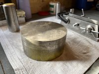
UNADJUSTEDNONRAW_thumb_1ecf.jpg

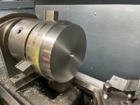
And here it is just fitting into my 3 jaw - only taking light cuts for now!
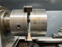
UNADJUSTEDNONRAW_thumb_1ed0.jpg

The base will be machined to match the current compounds contours and have a central locating pin press fitted again to match the current set up. The four T nuts will be used to secure this to the cross slide as per the original which I think should be plenty to hold it down securely.

I will do the basic lathe work on the 135 and then head over to a friends to use the mill to do the fun parts.
 
Last edited:

marcsO

Cast Iron
Joined
Mar 24, 2020
Location
SURREY
The round base section is now to diameter, the centre locating pin hole is machined, this will take a stepped pin that interference fits into the tool post base and locates in the hole in the cross slide, next job is the get the pin turned so its a perfect fit in the cross slide.

Once the item is finished I am looking to apply a finish to the part, possibly a tumble finish (like a sand blast) but open to suggestions as to what you think would be best and look in-keeping.

Solid Toolpost Holder 4.jpg
 

marcsO

Cast Iron
Joined
Mar 24, 2020
Location
SURREY
Location pin now done and pressed into the base of the disc, the next stage will be to order the Multifix E and holders so that the final height of the solid tool post mounting can be decided and then its off to the milling machine and maybe also the surface grinder :)

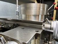
Dropped into the location hole on the cross slide for test fit, will remove another 1mm from the diameter as the edge of the machined disc is just proud of the end edge of the cross slide.UNADJUSTEDNONRAW_thumb_1ede.jpg
 

marcsO

Cast Iron
Joined
Mar 24, 2020
Location
SURREY
Been doing a little work in the background on the fixed tool post mounting which is being CNC'd this week but in the meantime have also been making a tailstock Morse taper ejector.

As I understand Schaublin did offer one as an accessory but was not able to find an original so decided to make a version. A member of this forum sent me a picture as the drawing I had did not make complete sense and if you are anything like me I need to see things rather than look at 2D drawings :)

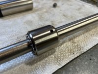
The item consists of a plunger which pushes the morse taper from the back, this is located and prevented from rotating by a pin (in my case a machined bolt end which runs in a short slot cut into the lower side of the tailstock spindle. This plunger is internally threaded, I chose M16x1.5mm as a fine pitched thread. A shaft is threaded to suit, then fitted and supported by a boss which is fixed to the shaft by a pin, that then faces onto a thrust bearing that is pushed against a fixture which screws into the end of the tailstock shaft. The shaft is rotated and plunger is pushed by the threaded rod against the morse taper and ejects it.

I have yet to decide on a handle style to spin the threaded rod, not sure what the original used but the drawings seem to suggest it was a large Allen key, mine will be either a wheel, lever or ratchet.

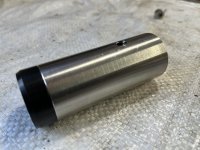
This is the plunger with a delrin end cap machined to fit a recess on the end to 'soften' the push end, may make one from brass depending on how it holds up.

UNADJUSTEDNONRAW_thumb_1f16.jpg

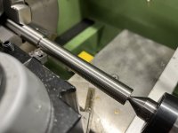
This is the M16 x 1.5mm thread rod in the scratch cut stage, the rod will be trimmed to the right size as its over long now ..

UNADJUSTEDNONRAW_thumb_1f13.jpg

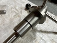
This is the fixed boss which is roll pinned through the shaft so it rotates and pushes against the thrust bearing which in turn pushes on the housing which is bolted to the end of the tailstock shaft by three cap head bolts ..

UNADJUSTEDNONRAW_thumb_1f19.jpg

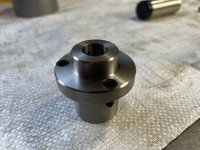
Housing with three countersunk holes for the mounting bolts ..

UNADJUSTEDNONRAW_thumb_1f17.jpg

All the items bar a handle or lever (yet to be decided) maybe someone can suggest the best solution for ease of use and leverage?

UNADJUSTEDNONRAW_thumb_1f14.jpg
 

marcsO

Cast Iron
Joined
Mar 24, 2020
Location
SURREY
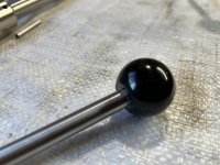
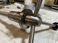
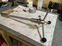
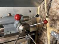
Made a decision based on what I could make rather than what maybe would be the right way... either way I decided to mimic the star wheel type handle system which is a ball on the end of an arm.

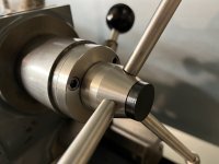
Machined up a small hub with a slanted face to mimic the star wheel design, rather than 4 handles have gone with three mainly as space was not there for 4 arms. Had to drill the holes by using a spirit level to achieve a 90º result with a 6.8mm drill so the final tapped hole was M8. The arms are 100mm long stainless with 30mm OD bakelite balls with threaded inserts fitted, these are the same items used to replace all the balls and some arms on the 135 and were all from WDS components.

The three arms also locked the rotating shaft to the handle, to achieve this I drilled the holes through the hub into the shaft by roughly 4mm and machined a corresponding 6.8mm OD section to the end of the M8 threaded end of the arms so they engaged the shaft at three places.

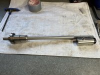
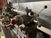
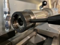
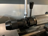
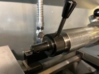
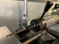
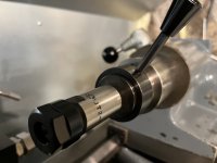
The overall completed tailstock morse insert release works well and the leverage on the handles is moderate helped by the fine pitch M16 thread on the shaft.

Some pictures of the finished item follows.

Work on the solid tool post continues and will be posted here when the machining has been done.

Happy New Year all.

UNADJUSTEDNONRAW_thumb_1f2b.jpgUNADJUSTEDNONRAW_thumb_1f30.jpgUNADJUSTEDNONRAW_thumb_1f31.jpgUNADJUSTEDNONRAW_thumb_1f32.jpgUNADJUSTEDNONRAW_thumb_1f33.jpgUNADJUSTEDNONRAW_thumb_1f34.jpg
 

marcsO

Cast Iron
Joined
Mar 24, 2020
Location
SURREY
Thank you Ole, just need to make a small black plastic cap to cover the exposed shaft end and it's complete.
 

marcsO

Cast Iron
Joined
Mar 24, 2020
Location
SURREY
Badly made delrin cap to cover the end of the hub and shaft, will make a better one once I have finished insulating and boarding my workshop and fitting the light back over the lathe!

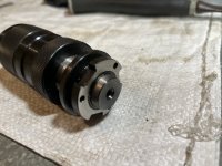
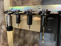
Not sure if many of you have heard of Arrand tooling but a guy many years ago set up this business and sold all sorts of parts to make machining easier, sadly he has wound the business down following retirement and has some limited stock left but a while ago I bought two MT3 quick release holders and some attachments to allow a quick release chuck to be used, spotting drill holders and two normal drill holders for common size holes, believe there is still some stock of the parts in the UK if anyone fancies some very well made and useful quick release tailstock holders for various common jobs.

Pictures of the end cap and the Arrand holder and some attachments .....

UNADJUSTEDNONRAW_thumb_1f3d.jpg
UNADJUSTEDNONRAW_thumb_1f39.jpg
UNADJUSTEDNONRAW_thumb_1f38.jpg
UNADJUSTEDNONRAW_thumb_1f3a.jpg
UNADJUSTEDNONRAW_thumb_1f3b.jpg
UNADJUSTEDNONRAW_thumb_1f3c.jpg
UNADJUSTEDNONRAW_thumb_1f35.jpg
UNADJUSTEDNONRAW_thumb_1f36.jpg
 

marcsO

Cast Iron
Joined
Mar 24, 2020
Location
SURREY
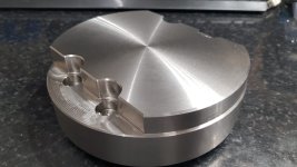
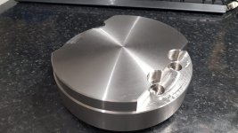
Main solid compound machining done, hope I have measured correctly for the 'E' Multifix tool holder etc to sit at the right height for 20x20mm tooling - time will tell!

Need to dress the flat milled surfaces, probably use wet & dry unless someone can suggest another method, sadly don't have a fly cutter so the machining is done with a normal carbide milling bit hence the lines.

Next job is raid the kids piggy bank and drop a line to Pewe tools .......

PHOTO-2023-01-03-15-08-26.jpgPHOTO-2023-01-03-15-08-27.jpg
 

devarda

Plastic
Joined
Feb 1, 2015
Nice work with your machine. This is an excellent reference for all owners of 135 owners who need to work on the variator/leaks etc.

I recently bought a 150 ontop of already owning a 135 so now I can go back and sort some issues (like still a small oil leak 🙄) and other repairs but still have a similar lathe running simultaneously. I wouldn't have believed it but the 150 is really a better machine in design in many small ways so maybe I'll do some of these small upgrades to the 135 as well if I have time (minus the rapids!). I'll be keeping my compound slides as they're more than rigid enough for me hehe.

Good job with it all and thanks for sharing.
 

marcsO

Cast Iron
Joined
Mar 24, 2020
Location
SURREY
You are welcome and whilst my knowledge of lathes is not great the task to design and make a revised Variator was a nice project, to get a solution somewhere close to Schaublins later version was the goal and so far it's holding up well.

On the 150 I doubt you will ever need a solid compound but again my goal was 'experiment' and sadly the compound that was made for the larger Multifix toolholder system which this machine needs is just not available.
 

marcsO

Cast Iron
Joined
Mar 24, 2020
Location
SURREY
I would be interested to hear about the design improvements on the 150 if you have a moment to explain them?
 

marcsO

Cast Iron
Joined
Mar 24, 2020
Location
SURREY
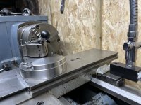
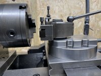
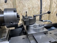
Collected the solid tool post yesterday and popped it on the cross slide for a mock up, placed my Multifix A on top. Seems to me the lowered top surface should now suit the E which is overall a tad larger (that was the plan!).

Need to get new fixing bolts as the originals are too short and might also contemplate 3D printing two covers to clip on the sides covering the bolt holes and shaped to follow the contours of the part - might even try to add the 'Schaublin' name to these as well for some pointless reason :)

UNADJUSTEDNONRAW_thumb_1f5a.jpgUNADJUSTEDNONRAW_thumb_1f58.jpgUNADJUSTEDNONRAW_thumb_1f59.jpg


Top