What's new
What's new

Project Schaublin 135

marcsO

Cast Iron
Joined
Mar 24, 2020
Location
SURREY
A short pictorial of the Variator bearing and assembly detail, if I get the time I will shoot a video of the process to re-fit the Variator and belts so its more obvious as to how things have been designed - naturally this all hinges on the final item being successful in its re-design and all the parts fit and go together!

The first task is to slide the new shaft into the Variator yoke from the door end on the motor cabinet so its easy to do rather than have to come in from the back end deep inside the bowls of the machine where access is all but impossible, major design criteria #1.

PHOTO-2022-07-29-12-22-09 2.jpg

As there are no bearings fitted at this stage into the yoke arm so the shaft is free to insert, the Variator assembly complete with belts looped over the pulleys is then held between the yoke arms and the shaft passed through the seals of the Variator and out the other end. The small insert which forms part of the slip ring is already bolted on, this holds the end pulley flange to the assembly during assembly.

PHOTO-2022-07-29-12-22-09 3.jpg

The end of the shaft can now be tapped through and into the bearing races pressed into the yoke arm opposite the opening, the shaft will seat on the bearings as it has a step machined into it.

PHOTO-2022-07-29-12-22-09 4.jpg

To hold this from moving outwards there is a washer and bolt fixed into the shaft hold it in place

PHOTO-2022-07-29-12-22-09 5.jpg

Once this is done the shaft is 'fixed' at one end and now you can slide in the two bearings into the yoke at the insert end, these are push fit. They are secured by a pressure ring holding the bearings in place and then a washer and bolt are added to finalise the shaft installation.

PHOTO-2022-07-29-12-22-10.jpg

PHOTO-2022-07-29-12-22-10 2.jpg

PHOTO-2022-07-29-12-22-10 3.jpg

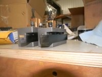
The Variator slides fore and aft on the shaft and during the re-design we (hopefully) worked out that there should be enough space to position the split ring over the shaft and align with the insert which is already fixed in place and fit the three bolts, this process might be the only fiddly part but I'm hoping as the insert is already fixed the hole alignment should be good and therefor the bolts should go in fairly easily, once in they are nipped up with an Allen key and some thread lock added beforehand.

These images show the movement available for the Variator self alignment and the completed fitment of the split ring.

PHOTO-2022-07-29-12-22-10 4.jpg

PHOTO-2022-07-29-12-22-10 6.jpg
 
Last edited:

marcsO

Cast Iron
Joined
Mar 24, 2020
Location
SURREY
Working on wiring in various forms so not super exciting but has to be done.

The phase convertor requires as mentioned in post 191 a breaker to protect it from any issues generated in the lathe, in addition they say you should also be able to isolate the mains supply to the phase converter so you have the ability to disconnect the lathe and convertor from the supply board via a switch placed in an accessible place - well all that needed really to go in the phase convertor so found some space for the breaker inside as it does not need to be outside, if it trips then I will isolate the power and open the door and re-set.

The isolator I fitted to the front door so its kept neat and all contained in the unit.

Also started the main lathe wiring, connected up a large rubber feed cable to the 135 via the inlet point, drilled and tapped a couple of M5 holes to take cable supports so the cable is kept off the floor and run along the back of the machine to the end where the phase convertor will be mounted eventually on the wall and its motor somewhere else!

IMG_4541x.jpgIMG_4542x.jpg

IMG_4543x.jpg

IMG_4545x.jpg
 

marcsO

Cast Iron
Joined
Mar 24, 2020
Location
SURREY
Need your help guys ....

I only took one picture of the wiring connection before removing the knackered old three way fuse box and its not clear from this picture on how the wires are connected, as you can see from the picture there are 4 wires leading back to the electronics section of the lathe but the question is which is which in terms of function, can somebody please advise?

The wires on the RHS are my new feeds, brown/black and grey are the 3 phase L1/L2/L3 feeds and the blue is neutral, earth is connected directly to the chassis as you can see. Which goes to where?

IMG_4544x.jpg
 

marcsO

Cast Iron
Joined
Mar 24, 2020
Location
SURREY
Asked the question to a friend from Germany who suggested the cable in the pictures is not original and probably not the right size either, he said trace it back to the connection panel at the base of the front electrical cabinet and this will show which is connected to which.

These was simple and really should have done this myself, either way the 135 is wired 3 live feeds and earth with no neutral, just checking if there is a bias on the live feeds with two phases driving the master switch and e-stop as these should be wired to the two 'real' phases from the converter as they are more voltage/current stable and the not the generated phase which can fluctuate, once I have checked this will replace the wire feed with a new 4 core rubber sheathed cable and connect up the feed/supply via a ceramic 52A 4 way connector block.

Here is where the wires terminate, red to R, yellow to S and blue to T - black is neutral. I have also asked what should be the colour scheme of cables used although this may have changed in the 50 years since this machine was made ...

IMG_4546x.jpg
 

marcsO

Cast Iron
Joined
Mar 24, 2020
Location
SURREY
Control live feeds are S & T so if anyone is connecting a phase convertor the two genuine phases need to be connected to these two connections and the third generated phase to connection R.
 

marcsO

Cast Iron
Joined
Mar 24, 2020
Location
SURREY
Hi well finally the day came to hook it up to the rotary phase controller and pray that there were no pops, bangs, smouldering wires and that the motors (all three) worked.

Firstly bought a 53A rated ceramic 4 way connector and bolted this to the base of the relay cabinet where the 4 core power feed comes into the machine, routed new cable down to the connecter strip in the front electronics cabinet so the wiring was new and of the right gauge, crimped ferrules to the cable ends and connected up the feed and delivery cables.

IMG_4553x.jpg

IMG_4554x.jpg

Wired up the phase controller and plugged everything in, power on and nothing on the lathe, dead, a few minutes of head scratching and then realised I had not thrown the 20A breaker I fitted into the phase controller - doh!

Second time power on and the oil pump whirred into life, what a lovely sound and one ticked box, tried the coolant switch, bingo this was up and running too so now just the main motor.

We decided not to instal the Variator until we had tested the main drive motor, played around with the dials and dropped the lever down, success the motor sprang into life, whilst playing around have found the pressure switches on the tumbler need adjusting but that seemed to be the only major issue.

With that all working we tackled the Variator which has been a key element to the whole project aside of the general clean up. Firstly the yoke went in and the large shaft which supports it was lubricated and slide through with some jiggling as there are two spacer rings that go each end so once the yoke is fitted it can be positioned to give the right placement for the Variator. Fed the speed control worm screw into the brass driver which is fitted to the yoke, a two person job as one turns the speed wheel and the other aligns the threaded screw with he driver, once on the stop was fitted so it would not drop off.

The new Variator has a specific installation process, its 1000% easier than the original but still takes patience and a bit of blind surgery.

We wound the yoke right up to its highest position, this you have to do to be able to get the spindle belt over the Variator pulley, this being the first job, once on the Variator hangs by itself, drop the motor belt over the other pulley. Drop the yoke down so the shaft holes are roughly in line with the Variator and then feed the new shaft through the Variator and into the pressed in bearings at the far end, things are then self supporting.

Push fit the two bearings on the front of the yoke and fit the shaft retaining bolt and washer onto the back of the shaft, its not visible but easily found and done with some finger juggling and a normal Allen key.

Next is the front bearing retaining ring and the 5 x M3 bolts and then the other shaft retaining bolt and washer.

Back to the rear of the Variator and fitting what we call the 'Pac Man', this split ring dog detailed in earlier posts slides into place over the flat portion of the shaft and as it can only go on in one position the bolt holes sign up automatically, fitting the 3 bolts is a little tricky but a shortened Allen key gets them all done up and tightened up. Once done the Variator can be physically slid back and forward on the shaft to allow the belts to self align. Before we installed the Variator we greased the sliding centre section via the grease nipple and plugged the vent hole with a stepped grub screw, this should not need re-doing for a long while.

There was a need to lift the main motor up to get the drive belt in place so this was done by unbolting the adjustable support tensioner and lifting the motor up with a length of wood and dropping the belt over the pulley, once done the support was bolted back in place and adjusted.

The main motor has lateral movement too on its shaft which allows you the option to get the drive shaft nicely aligned to the Variator, once done its nipped up with a grub screw (not to be forgotten when adjusting the motor tension later as the belts slacken!).

Topped up the oil reservoir and hit the go button, a few minutes of new belts and cleaned pulley noise subsided into what I consider to be a fairly quiet belt drive system. You can see the Variator slide on the shaft during speed changes using the wheel which is good as this was a discussed point earlier in the thread, everything seems to spin nicely and so far no oil leaks from any of the new push fit fittings etc which is a joy. Oil seems to be re-circulating which is positive.

So the initial outcome seems positive and the system seems to be working as designed, a little work to fix the pressure switches on the tumbler is required and will then do some measurement tests on spindle and ways etc to see what this machine delivers and how worn parts might be.

IMG_4559x.jpg

IMG_4558x.jpg

IMG_4557x.jpg

I shot a couple of short video clips but need to work out how to post as you cannot simply upload them like a picture, I'm guessing they need to be saved to a support platform and a URL link added once done - any help on this would be welcome.
 

marcsO

Cast Iron
Joined
Mar 24, 2020
Location
SURREY
A couple more videos now that I have the hang on how to post them and do the transfer.

This one shows the Variator being adjusted for speed via the hand wheel, some belt noise which I am guessing is normal for this but overall the transition seems good.

One note and it might be something we re-visit is the large brass pulley carrier assembly in its original form spun around the fixed hardened shaft, over time oil contaminated the belts the user has obviously tightened them in an attempt to stop the issues of slippage, this would have applied heavy loads on the brass sleeve on the shaft and when we took the assembly apart the brass sleeve was not perfectly round on its internal bore, wear had made it slightly oval. It's noticeable now in the set up we have in that this generates a slight 'clicking' noise as the slight movement generates this noise on each rotation.

We may well make a new sleeve when we have the time but for now its perfectly fine just not quite 100%.


This second clip just shows the various carriage motion functions which seem to work as they should, the short selection lever will take some getting used to as it's a somewhat strange design, guess Schaublin were trying to squeeze all the functions into one control which for me makes it over engineered and somewhat complex - I'm sure it's fine but even watching some of the machine sellers videos from Germany and alike they all seem to struggle with this lever and the selection process, often yanking and getting frustrated with it ...


marcsO

Cast Iron
Joined
Mar 24, 2020
Location
SURREY
Hi all, does anyone have a 'User Manual' for the 135 as oppose to a Service Manual which I have, looking for the complete tutorial on how to use all the functions on the machine so I can make sure everything is working as it should, I know what I am doing and what to expect from the machine in terms of capabilities.

A friend who has been doing a lot of the machining work on the re-designed Variator asked me a question the other day, the answer to which I really did not know the answer, maybe someone can help .....

" Its a huge machine in terms of build, a big motor and massive tailstock yet it has a small tool post, swings a relatively small chuck and the height over the slide is very small for such a physically big machine"

So what was it primarily designed to do considering the above, there must be more than just accuracy .....?
 

marcsO

Cast Iron
Joined
Mar 24, 2020
Location
SURREY
I guessed a manual might be a tall ask, oh well trial and error (hopefully not too much of the latter!).

Be good to get some feedback on this topic - compound slide

Back when I was thinking about the compound slide, its cleaning and check over, the discussion around tool posts cropped up, the machine came with a Multifix (original) tool post and three holders, either way I would need more holders but there was a discussion around the Multifix A tool post being quite small for this machine, the challenge is the E which is the next size up (not original tooling however) is a struggle to fit as getting the cutting tip on the centre line is almost impossible unless you have the 'special order' Shaublin compound designed for the Multifix holder - the item is no longer made and I have never seen one come up for sale so what are the options:

- Wait to see if one does and pay silly money
- Make one
- Do away with the compound and just make a solid mount to take the E so it aligns for correct centreline


On: Wait to see if one does
Q: Does anyone have one for sale or know of one for sale?

On: Make one
Q: Does anyone have any drawings of the Schaublin Multifix compound slide? (I have been warned of milling the existing twin slot one down as it compromises strength and rigidity)

On: Do away with the compound slide....
Q: What are the pro's and con's to doing this?

Open to explore these options so looking for your help guys.
 

devarda

Plastic
Joined
Feb 1, 2015
I think I've mentioned this before but here we go again. I have 25 Multifix E holders on my 135 with the normal compound slide and yes you need the adjustment screw all the way to the bottom but 16mm carbide cutters fit. Some are just a tiny adjustment up, some are dead on and maybe one or two random brands I've put on the surface grinder to take off like. 1 or .2mm on the bottom of the shank.

Other than this fact it's a totally proportional toolpost for the lathe and the special compound was designed to take a multifix B toolpost which is a stupidly large toolpost for this lathe.

You could go with a solid toolpost but I think the compound slide is plenty rigid enough compared to other lathes like Hardinge etc and I use mine for cutting internal tapers etc far too often to consider removing it. I wouldn't modify the original compound slide myself.
 

beckerkumm

Hot Rolled
Joined
Aug 5, 2014
Location
Wisconsin Rapids WI
I have a Multifix A on my Smart Brown 1024 and an E on my CVA. The A allows the tool to rest about .03 lower than the E and IMO fits a 1/2-5/8 shank better. If you compound is less than 4" wide, and the motor hp is 3 hp, the A is sized more appropriately. The E can handle as much as 6 hp and 3/4" tooling fits very well as the depth of the holder is greater. If you do deep boring and want as much bar as possible the E is a better choice. DaveDSCN4218.JPG
 

Attachments

  • DSCN4219.JPG
    DSCN4219.JPG
    237.4 KB · Views: 2

marcsO

Cast Iron
Joined
Mar 24, 2020
Location
SURREY
I wouldn't modify the original compound slide myself

That is something I will definitely not be doing as I think I mentioned in my post, but appreciate the info around the E and fit. Having the tooling right at the bottom is good I guess for stability but be nice to have a little play downwards hence the questions.

Wow did not know the special compound was for the B tool post but guess back then the E was not an option - it's big as you say and way to big for the 135.

The A allows the tool to rest about .03 lower than the E

Not a big difference which is interesting, will have to do some measurements with my A in place and see how close it comes out. Motor on the 135 is a 2hp/4hp unit so again it sits in that area where the A meets the E in terms of size etc.

A solid tool post might be a good project, seen people design and draw one up in CAD, 3D print it to ensure it fits and works and then use the 3D part to make a plug for a cast tool post holder, would that be the best material to make one from or would a cnc cut billet of some metal be better?
 

beckerkumm

Hot Rolled
Joined
Aug 5, 2014
Location
Wisconsin Rapids WI
If tooling is limited to 5/8" and you have a multifix A, I'd not spend money to swap it out. I think you will find when using the lathe that the A fits the tooling and machine quite well and the post will handle the torque available . Dave
 

rotarySMP

Cast Iron
Joined
Mar 9, 2008
Location
Vienna Austria
Nice restoration you are doing there.
"So what was it primarily designed to do considering the above, there must be more than just accuracy .....?"
As I understand it that is it. It is designed to be so rigid, that you can hard turn to extreme accuracy, and avoid some grinding operations.
 

marcsO

Cast Iron
Joined
Mar 24, 2020
Location
SURREY
Hi sorry for a delay in posting but been away on leave and closed the workshop for three weeks and enjoyed not having to clean my hands from oil :)

So the update is the 135 is running, however there are a few items which remain non functional and the next tasks will be to establish what might be the causes and work through a process of elimination to fix them (hopefully!)

Maybe some of you Schaublin officionardo's might be able to give me some pointers.

OK first is the brake:

In this thread I removed the brake, serviced, remade the bushes, refaced the brake and cast iron disc and re-assembled. I checked the function by passing voltage through the coil and it worked perfectly, tested continuity too and all was good.

I did check the wiring on removal, just two wires and ensured they were re-connected in the same orientation as before. Sadly and it might just be something simple but when you move the lever to spindle stop no brake is currently applied.

So the question is what might be the checks needed to work out where the issue might be?

Second is the motor speed change:

When you select 11-11 on the dial you should get 5 positions on the lever giving 2 1 0 1 2, where 2 is fast, 1 is slow, zero is off (with brake) and the other direction is simply a reversed motor direction with slow and fast speeds.

I have not tacho checked the spindle speed so not sure if the current running is in fast or slow mode, really hard to tell, I think it's in slow speed as 3000rpm is quite a rate and the chuck does not seem to be really spinning fast when the speed wheel is rotated to give max rpm at the given speed range.

The motor coil all checked out fine when tested, and I did make sure the wires all went back where they came off, I can't however assume they were in the right place to start with as someone may have fiddled with them before I got the lathe. Either way is there a logical process to fault test items to establish what might be the cause?

The system as I believe has 4 relays and a selection system where microswitches ride on a cam, there are also contactors which I know can get corroded and not work so if anyone has some guidance that would be much appreciated and I will post the process here once I have some ideas to check through?

Keep those suggestions coming :gossip:
 

ole.steen

Hot Rolled
Joined
Jun 11, 2002
Location
Oslo, Norway
Marc! You have done a great job here! Re. the speed change: The wheel to the right of the front of the way casting is the speed switch limiter. Remember that the spindle engine has a 1:4 speed ratio! The wheel has several positions to limit the throw of the speed lever so that you don't inadvertently throw the spindle into high speed with e.g. a large, unbalanced piece in the chuck. The funcion of the limiter is depending on the different components of the mechanism being in good shape and correct alignment. A very common fault is the longitudinal slot in the operating rod running through the apron being worn, so that the function of the handle is differend when you move the saddle from center to the left and right positions, and general slack. This can be remedied to some extent by removing the rod, remilling the slot to a wider (even) with, and making a new, fitting stepped wedge. If the wear is not too bad, a realignment of the rod and linkage may be all it takes, or maybe a new wedge is sufficient to take out the slack.
The brake: Do you have the electrical ciruit drawing? The brake is supplied DC current through a fuse, a rectifier and an adjustable serial resistor. There is also an interlock switch on the rear side of the spindle housing. You need to follow the current with a meter to find the fault.
 
Last edited:

marcsO

Cast Iron
Joined
Mar 24, 2020
Location
SURREY
Ole appreciate the information and understand the potential issues around the lever, the slotted actuation rod and linkages, I suspect there is some play or that the microswitches are not set correctly on the cam which is actuated by the lever - some testing will occur to see what the play is like at points along the bed.

I will arrange a friend to come over and we can work through the brake circuit and check, I do have a full wiring diagram so ultimately we should fine any issues. The brake is not so critical compared to the motor speed selector but want to get both right naturally.
 

marcsO

Cast Iron
Joined
Mar 24, 2020
Location
SURREY
Has anyone cleaned these 6 contactors before and if so any pointers as to how and the best way?

IMG_4553x.jpg
 

marcsO

Cast Iron
Joined
Mar 24, 2020
Location
SURREY
I found some information on a thread from late 2016 about the same issue of the control lever and play arising from general wear over time which then impacts the function selection process.

The image is the complete electrical panel which appears to come out in one piece and if managed correctly can be left connected too. My first plan is to disconnect the control rod which pivots the cam and see if by moving it manually the desired function (speeds & direction) can be simulated and then depending on the outcome may decide to remove the electrical panel complete and do any tasks needed to replace and adjust etc.

I know a bolt has dropped behind the control panel and removing it would give a good opportunity to check the items out and re-do connections etc at the bottom where they are screwed into the long terminal block.

Still not sure on if the contactors can be cleaned hopefully someone will chime in on this one and give me some pointers, I would guess a more modern unit could be used to replace these if they are not serviceable?

Here is the removed image I found on a different thread which shows the whole electrical panels removed as one unit which looks like a great design and hope mine comes out as easily!

20160303084538-2646a060-me.jpg
 
Last edited:


Top