What's new
What's new

2001 Integrex spindle orientation clamp out of position

noname777

Cast Iron
Joined
Aug 24, 2018
Location
NSW , Australia
U have to have a test bar with a cut. This cut is supposed to be in parallel with true Y axis movement. All this is done to have the tool properly locked and oriented in ATC operation and it should also correct your issue with facing, in case when you face it you have little vestige and have to shim the tip.

Yes. The procedure looks tricky. I guess you have to estimate the amount you have to adjust, move it, assemble it and check milling tool clamp position. If you still out than you open it again and repeat every step again.

See, these procedures were not made to be given to customers, there are always little trick here and now Mazak personal uses. You, like running this machine in DEBUGGING mode with all interlocks ignored, or some other special parameter enabled.


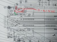
ok. I got it. Here is the correct parts manual page. No pins. U just have to adjust outer part of the coupling
 

Attachments

  • IMG20221121094216.jpg
    IMG20221121094216.jpg
    643.6 KB · Views: 3
Last edited:

JSL_MFG

Aluminum
Joined
Apr 24, 2022
I could be wrong, but wouldn't it be impossible to have a test bar clamped in orientation? In order to remove everything to access the index ring, you would no longer be able to have a tool clamped in orientation with Y. There's got to be another way to set the orientation of the index ring without having something clamped in the spindle at orientation.
 

JSL_MFG

Aluminum
Joined
Apr 24, 2022
procedures were not made
U have to have a test bar with a cut. This cut is supposed to be in parallel with true Y axis movement. All this is done to have the tool properly locked and oriented in ATC operation and it should also correct your issue with facing, in case when you face it you have little vestige and have to shim the tip.

Yes. The procedure looks tricky. I guess you have to estimate the amount you have to adjust, move it, assemble it and check milling tool clamp position. If you still out than you open it again and repeat every step again.

See, these procedures were not made to be given to customers, there are always little trick here and now Mazak personal uses. You, like running this machine in DEBUGGING mode with all interlocks ignored, or some other special parameter enabled.


ok. I got it. Here is the correct parts manual page. No pins. U just have to adjust outer part of the coupling
I agree! I just don't know how to make sure it's correctly positioned.. baby steps I suppose.
 

BOB-OO

Aluminum
Joined
Dec 5, 2010
Location
NE PA
It was a good while ago-10 years, but if I'm remembering correctly, there isn't one correct alignment, it was trail, lock, test, make small adjustment, retest. The important thing is the result, no movement when clamping. It didn't take more then an hour but the guy doing had a lot of experience. He explained that its like adjusting the peak to the valley of 2 intermeshing gears with rounded teeth, if the top of the peak doesn't meet the floor of the valley at encoder 0, then they move a bit during lock. Sorry never actually did it myself.
 

JSL_MFG

Aluminum
Joined
Apr 24, 2022
It was a good while ago-10 years, but if I'm remembering correctly, there isn't one correct alignment, it was trail, lock, test, make small adjustment, retest. The important thing is the result, no movement when clamping. It didn't take more then an hour but the guy doing had a lot of experience. He explained that its like adjusting the peak to the valley of 2 intermeshing gears with rounded teeth, if the top of the peak doesn't meet the floor of the valley at encoder 0, then they move a bit during lock. Sorry never actually did it myself.
So as of right now, I'm thinking about calling in a tech. Unfortunately, the index ring is really stuck on there, and I can't get any movement out of it. I suspect it's corroded and stuck in place.

I tried to put two bolts into it and use a slide hammer for popping it loose, but I'm worried about causing more problems. Pic attached for reference. Any tips on getting that sucker to loosen up? A service tech would be a 2-week wait, and I need to get this machine back in service.
 

Attachments

  • PXL_20221122_204444568.jpg
    PXL_20221122_204444568.jpg
    491.8 KB · Views: 6

noname777

Cast Iron
Joined
Aug 24, 2018
Location
NSW , Australia
I think you have to adjust smaller diameter part of it. Outer part of it is a lock for front bearings. It looks like
 

Attachments

  • pic1.jpg
    pic1.jpg
    657.7 KB · Views: 11
Last edited:

BOB-OO

Aluminum
Joined
Dec 5, 2010
Location
NE PA
Props to you for staying with it. I can't advise how to free it and I wouldn't hit my spindle with more then a tap either. Can you find someone-a service guy at Mazak to speak to you about it? They have 24/7 service guys who really know the equipment-they'll help even if you bought it used. With that picture I have to think somebody could walk you through it.
 

JSL_MFG

Aluminum
Joined
Apr 24, 2022
Props to you for staying with it. I can't advise how to free it and I wouldn't hit my spindle with more then a tap either. Can you find someone-a service guy at Mazak to speak to you about it? They have 24/7 service guys who really know the equipment-they'll help even if you bought it used. With that picture I have to think somebody could walk you through it.

My local Mazak tech support guy is an absolute unhinged douchebag. I've called other Mazak locations, and when I tell them my location, they try and send me back to this guy. If I say that I don't want to talk to that guy, he finds out about it and calls me and tries to intimidate me over the phone. I've never dealt with someone so unprofessional in my life. The first time I spoke to him, he started complaining about liberals and said "they should all beat their heads in with a hammer" within the first 3 minutes of the call - I was calling to ask about a thermal relay issue. I asked him on Friday if ANYBODY else could possibly give some input, and he says he's the only one I can talk to.
 

JSL_MFG

Aluminum
Joined
Apr 24, 2022
@noname777, you were right. I popped the screws loose on the smaller coupling, and it immediately had plenty of movement for me to adjust.

I'm going to give this a whirl and see what happens.
 

noname777

Cast Iron
Joined
Aug 24, 2018
Location
NSW , Australia
all mystery attached to any spindle is bearings preload. That is most complicated part of it, the rest is easy: AC motor spinning few KG of steel and PLG encoder tells where magnetic field needs to be at any given moment in time, if that is IPM motor :)
 

JSL_MFG

Aluminum
Joined
Apr 24, 2022
I'm back! I spent the last month messing with this thing, and this was a royal pain.

I gave up last week and called in a service tech. Two techs spent 8 hours working on it but couldn't align the couplings. Thanks to you guys, the techs said I knew what I was talking about. I watched what they did and kept trying to avoid another 2k service call; I finally dialed it in this morning.

Hopefully, this step-by-step process will help someone tackle this in the future:
  • Check spindle alignment with the milling spindle clamped. Measure the total variation across a calibration tool w/flat or high-quality tool holder. Identify which side is high and which is low to determine the direction to rotate the coupling. ( I got .005" across 2.5")
  • Remove the entire spindle cover to expose the two inner couplings. Place an indicator on one of the teeth of the main coupling - ideally on the backside of the tooth, depending on which direction you need to rotate the coupling.
  • Loosen one bolt at a time, and then snug it back down. Doing this one bolt at a time is important. If we loosen all the bolts, the coupling tends to lift a bit, giving you a bad indicator reading once you try and rotate it.
  • Use a brass punch to knock on one of the teeth to push the coupling toward the low side of the variation. Do this to a nominal number, such as 0.005."
  • SLOWLY tighten down the bolts in a star pattern. Watch the indicator to ensure you're not moving the coupling as you tighten the bolts.
  • Reassemble the spindle cover, turn it on and measure the orientation as stated in the first step.
  • Depending on your new measurement, you'll know how far you need to move the coupling to get your coupling dialed in. If you had .005" of variance, and moving the coupling by .005" now produces a variance of .0025, you need to rotate the coupling another .005.
  • Repeat the disassembly and adjustment steps, and check & repeat as needed. Don't keep trying if you're frustrated. This is a gentle process, so take a break if you're not getting where you want to go.
  • Once the spindle is aligned while clamped, adjust your spindle orientation parameter to ensure it's also properly aligned.
So really, the magic trick to this is identifying a pattern. Moving the coupling is MUCH more difficult than I had expected, but you'll be able to rotate it slowly by a few thou at a time. If you run out of movement and start hitting the bolts, you can adjust the coupling that rotates with the spindle. Rotate it in the opposite direction that you've been moving your coupling. This will screw up all the work you just did, but it allows you to push the coupling in the opposite direction.
 

noname777

Cast Iron
Joined
Aug 24, 2018
Location
NSW , Australia
It is interesting that MAZAK didn't use tapered pins in this particular design. Slight hit will move coupling and there you go, you start from the scratch.
This is how they work there, in permanent state of competition with OKUMA, DMG and NAKAMURA. Once project is released, they have only few people committed to support it or improve it, as they try to throw main force to create new project, to be able to be ahead of others.
You should probably align it as best as you can and after drill some holes and install tapered pins, on outer part of the coupling, you have plenty of spindles body to do it.
Although I am not sure if that helps, inner part of it is what always be stressed more.
 

Attachments

  • pic1.jpg
    pic1.jpg
    666.3 KB · Views: 4
Last edited:


Top