What's new
What's new

Has anyone built an LVDT amplifier/signal conditioner?

SeeFair

Plastic
Joined
Oct 20, 2015
Bob,
I enjoy reading your posts, and I appreciate your willingness to share your expertise. I always learn something.

Furthermore, you seem to be one of the nicest guys on pm, and one of few who actively tries to make it a more civil place.

As far as I'm concerned, you have nothing to prove.

I'm going to stop now because I'm starting to tear up.

Seriously, I've never met Bob, but that's what I see. For the op, I wish they sold self-awareness on ebay.
 

ballen

Diamond
Joined
Sep 25, 2011
Location
Garbsen, Germany
I'm picking up on this thread because I have a related question.

At some point in the future, I want to build my own readout/signal conditioning unit for Talyvel clinometer heads. Ideally I'd like a SOC solution that interfaces directly to the LVDT and has the ADC and DSP stuff on a single chip. Google immediately found the TI PGA970, which costs about $16 in quantity one. Does anyone have some experience with these? At least on paper it looks promising. Description cut-and-pasted below. Cheers, Bruce

[EDIT NEXT DAY]
A couple of notes on pricing and availability. Mouser's price for the PGA970 chip is 21 Euro/USD in quantity one. This is in stock in the USA and Europe in an HTQFP-48 package - a square outline with 12 SMD pads per side, easily mountable on a 1-sided prototype-friendly PCB. The development board PGA970EVM costs 233 USD or Euro in quantity 1. This is in stock at Mouser both in the USA and Europe. Digikey does not stock either item. I also don't find either item for sale via Ebay.

Description for the PGA970​

The PGA970 is a highly integrated system-on-chip LVDT sensor-signal conditioner with advanced signal-processing capabilities. It contains a three-channel, low-noise, programmable-gain, analog front end that allows direct connection to the sense element, followed by three independent 24-bit delta-sigma ADCs.
Further, the device contains a digital signal-demodulation block that interfaces to an integrated ARM-Cortex M0 MCU, allowing implementation of custom sensor-compensation algorithms stored in the device nonvolatile memory. External system communication is achieved by using any of the SPI, OWI, GPIO, or PWM digital interfaces. Analog output is supported through a 14-bit DAC and programmable-gain amplifier offering reference or absolute-voltage output. Sensing-element excitation is achieved by the use of an integrated waveform generator and waveform amplifier. The waveform signal data is user-defined and stored in a designated RAM memory area.
Besides the primary functional components, the PGA970 is equipped with additional support circuitry. The device diagnostics, sensor diagnostics, and integrated temperature sensor provide protection and information about the integrity of the overall system and sensing element. The device also includes a gate-controller circuit which when used with an external depletion MOSFET can regulate the device supply voltage in systems where the supply voltage exceeds 30 V.
 
Last edited:

SeeFair

Plastic
Joined
Oct 20, 2015
Looks more than promising. Thank you for finding that.

I struggled with the adjustable offset a lot with my analog implementation, trying to keep offset constant as the user changed gains, so that one could easily adjust the probe mechanically and get the readout on-scale at the highest gain. Much easier digitally.

Programmable power, bandwidth were not much worth thinking about back then, but your problem is going to be how to keep it simple.
 

SeeFair

Plastic
Joined
Oct 20, 2015
As I think back on this, when you look at the lvdt secondary on a scope, it is crying for a high-q bandpass filter (basically a resonant filter). You can't do it the analog world because of drift. If that device uses the same time base for excitation and detection, it should be possible?
 

rhb

Aluminum
Joined
Apr 27, 2019
Location
A small town in central Arkansas
Nobody has any experience with it other probably than TI engineers. It's *very* new, as in "not yet available". I'm going to request samples next week.

It's a very interesting chip, though the available data is a bit skimpy. It looks pretty much ideal to connect to any WiFi capable SoC.

It's got 3 separate ADC channels. It doesn't say what the sample rate is, but in any case that permits simultaneous reads of the 3 windings. From there you can do anything you understand well enough to code.

@SeeFair Are you saying analog frequency drift was a problem at a few kHz? Tracking audio filters are not difficult, but significant drift shouldn't be an issue. Many years ago I built a 40 m VFO using a JFET and BJT which was extremely stable. Basic ARRL circuit. A well built Wein bridge shouldn't have any stability problems.

For something like a DIY Talyvel, the readout doesn't need to be very sophisticated as you can recal by reversal in seconds. So despite the PGA970 being what I intend to use for a lab instrument, I'm still interested in circuits that will turn a cheap ebay LVDT into a precision electronic level. Less for my use than for the benefit of others. A DIY arc second electronic level is ~$100 if you know how.
 

ballen

Diamond
Joined
Sep 25, 2011
Location
Garbsen, Germany
Nobody has any experience with it other probably than TI engineers. It's *very* new, as in "not yet available". I'm going to request samples next week. It's a very interesting chip, though the available data is a bit skimpy. It looks pretty much ideal to connect to any WiFi capable SoC. It's got 3 separate ADC channels. It doesn't say what the sample rate is, but in any case that permits simultaneous reads of the 3 windings. From there you can do anything you understand well enough to code.
Are you talking about the PGA970? The TI "New Products" page listed it on 21 July 2017, and the most current revision of the data sheet is dated April 2019. The chip is in stock at Mouser both in the USA and Europe. There is plenty of discussion about it at the e2e.ti.com web site starting about four years ago. So I don't think the chip is "very new" and/or "not yet available".
 

SeeFair

Plastic
Joined
Oct 20, 2015
Are you saying analog frequency drift was a problem at a few kHz? Tracking audio filters are not difficult, but significant drift shouldn't be an issue.
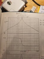
You are right, for the average lvdt application, and average bandpass filter with corner frequencies far from the carrier, drift is not an issue. Most applications probably just AC couple the input (high pass filter); the demodulator and back-end low pass filter cures all noise. But if you want to squeeze everything out of the device, and particularly if you want a high-bandwidth, low-noise lvdt, you might use a high-q bandpass filter on the front end to kill the noise without relying on the slow low pass at the back end. The demodulator is sensitive to amplitude AND phase. Changes in gain of the front end filter will directly masquerade as the displacement you are trying to measure, and phase not so much (I think it's a cosine function). But a high-q filter has very abrupt changes in amplitude and phase at the center frequency. A high-q filter based on R's and C's is just way too sensitive to those R's and C's.

For clarification, I'm attaching an ancient bode plot of a relatively low-q bandpass filter that I used for other purposes. Now imagine the center frequency drifts. The gain curve should give you pause, but look at the phase transition. And understand that for signals 90 degrees out of phase, the gain of the demodulator is... zero. The higher the q, the more abrupt the changes in both gain and phase.

So it you can't do it with the analog approach, at least for any significant q. But if the oscillator and the filter are digital and based on the same time base (as in the TI chip), they should track (no drift). The point I was trying to make is that the TI chip should open up some interesting opportunities.
 

Attachments

  • 20221211_080717.jpg
    20221211_080717.jpg
    284.4 KB · Views: 4

rhb

Aluminum
Joined
Apr 27, 2019
Location
A small town in central Arkansas
Are you talking about the PGA970? The TI "New Products" page listed it on 21 July 2017, and the most current revision of the data sheet is dated April 2019. The chip is in stock at Mouser both in the USA and Europe. There is plenty of discussion about it at the e2e.ti.com web site starting about four years ago. So I don't think the chip is "very new" and/or "not yet available".
Well the TI product page has only a partial datasheet and calls it a "new product". I did eventually find the user manual, etc and indeed it is several years old.

I checked both Mouser and Digikey and both had 0 in stock. I'll buy a couple in a heartbeat if I can find them. They solve the issues that make the AD chips unattractive.

I'll place a backorder with one or both suppliers if I can't get chips from TI.
 

ballen

Diamond
Joined
Sep 25, 2011
Location
Garbsen, Germany
How frustrating! When I first checked out the PGA970 on Friday, three days ago, it was in stock at Mouser in the USA (11 parts) and in Germany (7 parts). Now it's out of stock at both locations. Mouser currently shows a lead time of 98 weeks, which is not encouraging. Digikey also shows a ship date in March 2024.

Please let me know if TI can provide samples. If so, I'll also request a couple.
 
Last edited:

rhb

Aluminum
Joined
Apr 27, 2019
Location
A small town in central Arkansas
My Daytronics 300A arrived, but the beautiful 7" panel meter had a broken needle :-( It reads to 1 microinch.

As expected it's a tube Wein bridge and what appears to be a VTVM with a voltage reference. Five tubes, 3 transformers, 3 electrolytics and a light bulb. Two of the electrolytics are bad. I think I have most of the tubes it uses.

Hopefully I'll succeed in replacing the broken needle. The original is a ~0.03" metal tube. I plan to solder an 0.025" guitar string in it's place.

The voltage divider for changing scales is made from 0.5% wirewound resistors. So it's quite nice, especially if they were hand matched.

I'm going to get it working and see how a mid-50's gauge amplifier performs. I also have a Schaevitz ATA 2100 coming which is a bit more modern.

I've not chased TI yet. Worked on other projects.
 

rhb

Aluminum
Joined
Apr 27, 2019
Location
A small town in central Arkansas
Daytronics can provide no information, but it's simple enough I can fix it w/o a schematic. They indicated that it's a 70's design which I find really surprising. I suspect he's mistaken. It's using a tube rectifier which would be unthinkable in the late 60's.

I'll be documenting the 300A repair on EEVblog.

I received my $100 ebay Schaevitz ATA 2001 today. I rezeroed it to an offset of less than 0.1 mV. Once I find a large analog zero centerpanel meter that will become my B&S 599-988 readout until I find a 599-1021 for a similar price.
 

fobyellow

Plastic
Joined
Mar 9, 2021
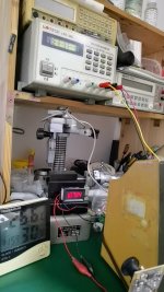
Try a Mitutoyo 519-401/402/411/403/413 manufactured after 1990, they are designed for half-bridge sensors, the critical parts are build on ceramic-substrate, it has a good temp-drift performance, if you want more, replace the 3 1/4W dip resistors around the sine generator with foil resistor(low temp-coefficient). i tried 401 and 411, and the final result is <1nm at 200um range(the repeatitivity is 0.05um due to the spindle and contact of probe).
To achive this, you have to get far away from the sensor and meter, cover the sensor and stand and sample to keep away from air convection, wait for the heat balence patiently for about hours if you touched any of them.
the sync-rectifier scheme are finished nearly 1 centry ago, nothing new, but the meter parts keep progressing, so you can start from any amplifiers build by Mahr TESA Citizen Mitutoyo Marposs BS Solartron after 1990, the analog part is already very good, but at that time, a high resolution ADC is very expensive, but cheap today. good luck

2.jpg

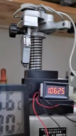
i use the mitutoyo 519-321 lever probe(the pen probe also works), the result is 1.0625um, the p-p noise is around 1nm
1.jpg
 

fobyellow

Plastic
Joined
Mar 9, 2021
if you want to log the data to computer, the best choice is solartron orbit, try DP*05/1/2/5, which are digital sensors, and you need a RS232IM or USBIM to connect to computer, the PSU is not necessary , you can get 5v from any phone charger. they can achieve 18 bit resolution,and 16-bit noise free ferformance, and solartron provide a free software from their website
 

rhb

Aluminum
Joined
Apr 27, 2019
Location
A small town in central Arkansas
I can get 40 ppm accuracy from an HP 34401A and a Keysight 33622A (at 50 readings per second via GPIB IIRC :-) The rate limitation is the integration time for the 6.5 digit ADC.

I found a 7" meter from a Daytronics 300D on ebay. Very nice with an aluminum housing. So I just need to sort out the scale range switching to feed the meter and source the precision resistors.

With stuff like the ATA 2001 as cheap as they are I can't imagine building one except as an amusement a la "Max Wein, Mr. Hewlett and a Rainy Sunday Afternoon" by Jim Williams.

I ordered sockets to fit the B&S 599-988 connector so I can connect the B&S RVDTs to other stuff. Unfortunately, they're coming from Italy so it will take a while.

This will really get to be fun when I get a laser interferometer set up with which to test the various LVDTs and RVDTs I have.


Top