A couple of more updates. First, regarding the problem that I brought up in post #14, the cause and the solution are both simple. Fortunately it doesn't indicate any significant abuse and did no damage.
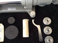
The crosshairs target and the reticule are each moved along one dimension on a separate small linear slides. Shown below is the horizontal slide for the crosshair target, which is on the optical window. The (vertical) slide for the reticule is identical, but not visible here.
Below, you can see that there is a separate lead screw for the slide and for the 0-10 minutes indicator. In this photo, the lead screw for the indicator is visible at the top of the enclosure. Below it, near the left end of the screw, is the indicator itself, which has a vertical white line. Also visible, through the right end of the round glass optic, is the lead screw for the slide:

(Off-topic questions for people here: What's the white stuff visible on both springs above? Should I clean it off? How? What -- if anything -- should I use to lubricate the squeaky mechanism? I don't want to dirty or damage the optics.)
The lead screw for the slide is the central long shaft visible below. The lead screw for the indicator is driven by the small gear on the top.

The adjusting wheel drives the crosshair lead screw through the central hole, and drives the scale indicator lead screw via the brass gear:

There is no key or other feature to maintain the orientation of the central shaft on the adjusting wheel. So at some point in the past, the central wheel must have slipped on the shaft, but the scale indicator lead screw continued to turn, so the two of them got mis-clocked. Simple solution, loosen the screw that holds the adjusting wheel on the shaft, and spin it to move the indicator to the correct position. Then retighten the central screw that retains the adjusting wheel on the shaft.
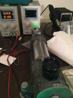
I've also continued to work on the illuminator. I decided to build a completely self-contained illuminator into the existing lamphouse. This consists of an 0-100mA constant current source, which will be driven from an 18650 Li-ion battery that I'll locate in a hollow under the base casting.

The circuit works as follows. The current through the LED passes through the transistor and the 1-ohm resistor to ground. So the 1 ohm resistor measures the current: 100mA of current creates 100mV on the resistor. The LM358 op-amp compares that voltage (- input) to the voltage on the voltage divider to the left. There, the 270 ohm resistor provides ~5mA of current that biases the Zener diode to 2V. The voltage divider made by the 100k and the 5k resistor give a range of 0-100mV on the central wiper of the potentiometer. If the voltage on the 1 ohm resistor (indicating current through it) is smaller than that set by the potentiometer wiper, then the opamp turns on the transistor, increasing the current flow. The circuit wastes about 5mA of bias current, but a single 18650 cell should still operate it for 20-50 hours depending upon the brightness setting.
[EDIT: it would probably be smart to add a Schottky diode in series with the battery, to protect against circuit damage caused by the user connecting the battery with the wrong polarity. There's enough voltage headroom in the circuit to accommodate a low-dropout 0.2V Zener.]
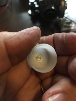
It's slightly like a ship-in-a-bottle construction. I moved the LED and holder to the lamphouse itself, so that there is no contact with the diffuser tube (they are 0.5mm larger ID)
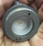

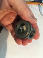
Here is the electronics. To set the scale, the shaft of the potentiometer is 6mm (1/4") diameter and the circuit board is about 21mm (13/16") diameter. The potentiometer for varying the intensity includes an on-off switch. The aluminum cap (threaded 3/4" x 26TPI) holds the potentiometer/switch internally, and the circuit board sits behind the LED.
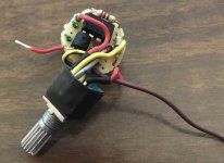


I'll drill a 4mm hole in the bottom of the lamphouse for a small power cable.
The circuit board isn't pretty , but it works correctly and fits in place, so for a 1-off I can live with it.
Cheers,
Bruce


