What's new
What's new

Fusion 360 WCS issue?

Sam I

Plastic
Joined
Nov 6, 2020
Hi Guys,

Not sure if I'm doing something silly or if it's some problem in Fusion or in my post.

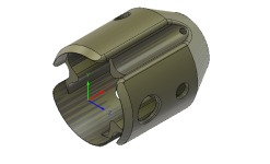
So I'm trying to machine a part on my HURCO VM10i with a 4th axis. Ignoring all the other features I've tried to do a simple spot drilling operation. I do the spot drill at the model WCS then create a pattern to repeat the same operation at two other locations 120 degrees around the part.

In the output G code the first hole looks good:

N90 G98 G81 X65. Y0. Z41.57 R51.472 F413.8

Much what I'd expect. The second and third holes are at different Y and Z locations though:

140 G81 X65. Y0.92 Z43.164 R53.066 F413.8

I then tried scrapping the pattern function and doing three drilling ops using the "tool Orientation" function in the geometry tab selecting the hole as my Z reference and I get the same issue. I've spent hours on this now and have absolutely no idea why it is doing this. Does anyone have any suggestions?

For reference, in the WCS for the main setup I have Y and Z zero at the A axis centreline, X zero at the face of the part.
1669408194894.png
 

LOTT

Hot Rolled
Joined
Nov 28, 2016
Is this your first time using this post and the 4th? Is "Use A Axis" selected in the post processor box? If it wasn't it should have failed I would think, but maybe not.
 

Sam I

Plastic
Joined
Nov 6, 2020
No, I've used this post a few times with no issue. Use A axis isn't an option in my post unfortunately.

I think I've worked it out to be due to my WCS origin - I had selected model box point however the model box point isn't exactly on centre hence why fusion tries to overcome this. As a workaround if I select stock origin instead it posts OK. Still a bit of a pain though as this is the 3rd op so the stock has been machined away. Not a huge issue but it would be nice to just set the G54 to the part face.
 

Cole2534

Diamond
Joined
Sep 10, 2010
Location
Oklahoma City, OK
No, I've used this post a few times with no issue. Use A axis isn't an option in my post unfortunately.

I think I've worked it out to be due to my WCS origin - I had selected model box point however the model box point isn't exactly on centre hence why fusion tries to overcome this. As a workaround if I select stock origin instead it posts OK. Still a bit of a pain though as this is the 3rd op so the stock has been machined away. Not a huge issue but it would be nice to just set the G54 to the part face.
Setting the WCS on parts that aren't cubic always take some fuckery in my experience. You'll pick orientation, then pick 0 but that fucks off the orientation into some random plane selection and then when trying to unfuck that other selections are fucked off into some nonsense.
 

gustafson

Diamond
Joined
Sep 4, 2002
Location
People's Republic
Does the simulation in Fusion look correct? If I were doing this as a dumbass with no 4th axis it would involve a different WCS for every hole as it is always going to drill in Z and Z is now at 90 degrees off.
 

memphisjed

Stainless
Joined
Jan 21, 2019
Location
Memphis
I have moved my model around in cad to get the origin to what I want wcs in fusion to be. The cam side has model origin as option for machining wcs.
I do not draw or edit in fusion- it is opposite intuitive for me.
 

cngbrick

Aluminum
Joined
Dec 22, 2012
Location
NB, Canada
I create an assembly with a face plate or chuck on axis and then import the part I want to mill and position it on the face plate. I use model coordinates. I keep reusing this assembly until it becomes too cluttered with parts.

RT
 

Sam I

Plastic
Joined
Nov 6, 2020
Does the simulation in Fusion look correct? If I were doing this as a dumbass with no 4th axis it would involve a different WCS for every hole as it is always going to drill in Z and Z is now at 90 degrees off.
Yes, the simulation looks fine, it's just in the machine it's off.

Have you tried creating a sketch point or a bit of geometry to set the origin? I have done this at times to better set the WCS origin.

That is exactly what I ended up doing and it worked perfectly!
 

Springy

Plastic
Joined
Oct 22, 2021
Yes, the simulation looks fine, it's just in the machine it's off.


That is exactly what I ended up doing and it worked perfectly!

For future reference, this is a common problem with parts like this, that are mostly a revolved profile but also has some asymmetrical machined features. What humans call the centerline of that part is the revolve axis, ie the center of the axisymmetric/turned features. Where Fusion considers the center to be is actually the center of mass - but you've got a big hole on one side, so that side is lighter. Using a sketch is the way to do it in this case. Fusion simulation won't catch the issue because it's pre-post-processing and its own toolpaths will work correctly with its calculated WCS, but on the machine you're setting the WCS to be along the actual real-world axis of rotation.
 

Sam I

Plastic
Joined
Nov 6, 2020
Thanks for that. It's good to finally understand the issue so I can avoid it in the future.
 

couch

Cast Iron
Joined
Jun 10, 2009
Location
Anaheim, California
In this instance, you could have set the stock in your setup as a cylinder and selected the WCS off the Stock Point rather than Model Point or Model Origin and not needed the sketch, but sketching points is often necessary.
 

Sam I

Plastic
Joined
Nov 6, 2020
In this instance, you could have set the stock in your setup as a cylinder and selected the WCS off the Stock Point rather than Model Point or Model Origin and not needed the sketch, but sketching points is often necessary.
Thanks, ended up doing a sketch in the end and using that. I did try setting my stock as a cylinder however it meant I could no longer use "Rest Machining" which resulted in some unwanted air cutting.


Top