What's new
What's new

Assembly Machining in SW CAM PRO

motofish84

Plastic
Joined
Feb 22, 2021
Hello,

I have been working in SW CAM Pro for over a year now running some prototype parts for my company.

We are a small manufacturing contractor and don't normally do much in the way of CNC machining until recently.

I have been doing smaller runs of parts with a single 6' vise and that has been ok. I want to utilize the "assembly machining" features available in SW CAM PRO to machine multiple parts on one setup however, I hit a couple road blocks last week.

Normally when I have a part requiring multiple operations I will simulate op1 and save the completed simulation model as a .STL file to use as my stock for the next operation.

When attempting to use the OP2 .STL file as my stock in an assembly for each of the parts, the stock will default to the assembly coordinate system and not the locations of the individual parts. If I use a standard stock bounding box, the "stock" or bounding box will locate correctly and in relationship to each one of the parts. When using the .stl file, there doesn't appear to be any way to modify the coordinate system of the stock to correct this.

Any insight??

Also, wondered if some folks might be able to point me toward any decent training resources (VIDOES, books, websites etc) that has some detailed info on Assembly Machining in Solidworks CAM? There's a few videos online but none seem to address subsequent part operations and utilizing .STL files

Thank you!
 

BluishInventor

Aluminum
Joined
Jul 7, 2020
When you save out your stock, you have an option to save it with whatever coordinate system you want. I don't remember if you have the option to select that same coordinate system when you pull it in, but it usually defaults to pulling it with whatever it was saved out in. So, if it's pulling it in with the Part's CS and putting it on the assembly CS, then just save it out with the assembly CS instead. The option for this is in the Save dialgue -> options(at the bottom), then select your CS at the bottom of the new window.

I remember having fun with this back in the day. It takes a minute to figure out.
 

motofish84

Plastic
Joined
Feb 22, 2021
When you save out your stock, you have an option to save it with whatever coordinate system you want. I don't remember if you have the option to select that same coordinate system when you pull it in, but it usually defaults to pulling it with whatever it was saved out in. So, if it's pulling it in with the Part's CS and putting it on the assembly CS, then just save it out with the assembly CS instead. The option for this is in the Save dialgue -> options(at the bottom), then select your CS at the bottom of the new window.

I remember having fun with this back in the day. It takes a minute to figure out.


Thanks for the reply @BluishInventor. You have helped me with SW questions in the past and I really appreciate you taking time to do so.

I went back to the OP1 Simulation and attempted to alter the CS. I do see the drop down for the output coordinate system however, the only option in the dropdown is "default"
 

len_1962

Stainless
Joined
Dec 1, 2008
Location
Tempe
Are all the parts the same? If so can you use patterning of the toolpath?

I don't use SWCAM I use HSMWorks, like it better, I do use Assembly machining all the time they do the same STL thing but I don't use it. I am pretty darn quick at modeling in SW, abuser since 1997, that I build my own solid for side2 and use that as my stock.
Again not knowing your part\s in the assembly hard to give a better answer to you.
 

BluishInventor

Aluminum
Joined
Jul 7, 2020
Thanks for the reply @BluishInventor. You have helped me with SW questions in the past and I really appreciate you taking time to do so.

I went back to the OP1 Simulation and attempted to alter the CS. I do see the drop down for the output coordinate system however, the only option in the dropdown is "default"

I guess i should've elaborated a tiny bit more. You have to create another Coordinate System(the solidworks command), and then reference that in the dropdown.

Since SW CAM uses association with geometry -> feature -> toolpaths and the like, associating your CAM coordinate system with an actual SW Coordinate system is really important. Is it necessary? No, as you can select geometry to place and orient the CAM CS with points and lines. But having it associated to a SW CS, allows you to manipulate the CS via the SW CS without conflict and everything downstream(which is literally everything) will give you less trouble later on.

Ever had to 'rebuild' the CAM side and then it wants you to re-pick the CAM CS? If you create and use a SW CS instead of geometry, that's shouldn't ever happen.

With regards to stock, you may have to create an additional CS for re-use in another setup/config/program to achieve proper alignment.

Another habit to get into is create a folder in the feature tree called CAM. Place any CSs and geometry that you use cam side that isn't used for the model explicitly.
 

Marvel

Aluminum
Joined
Jan 14, 2019
Location
Minnesota
I guess i should've elaborated a tiny bit more. You have to create another Coordinate System(the solidworks command), and then reference that in the dropdown.

Since SW CAM uses association with geometry -> feature -> toolpaths and the like, associating your CAM coordinate system with an actual SW Coordinate system is really important. Is it necessary? No, as you can select geometry to place and orient the CAM CS with points and lines. But having it associated to a SW CS, allows you to manipulate the CS via the SW CS without conflict and everything downstream(which is literally everything) will give you less trouble later on.

Ever had to 'rebuild' the CAM side and then it wants you to re-pick the CAM CS? If you create and use a SW CS instead of geometry, that's shouldn't ever happen.

With regards to stock, you may have to create an additional CS for re-use in another setup/config/program to achieve proper alignment.

Another habit to get into is create a folder in the feature tree called CAM. Place any CSs and geometry that you use cam side that isn't used for the model explicitly.
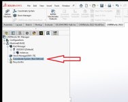
As @BluishInventor said, you have to create another Coordinate System and define it in your Operations Tree. This is key. I don't use Assembly Machining as much as I wish I did, there is a lot of benefits to Assembly Mode, even just programming a part on its own. There's a little more to setting it up than Part mode, and it seems to be a 50/50 chance I do it correctly.
It seems like if you have one thing off, it can mess up your whole set up definition from coordinate system to stock, from operation to operation. I've chased around CAM side being rebuilt and screwing up toolpaths, or coordinate systems moving because of a rebuild.
 

Attachments

  • Untitled.jpg
    Untitled.jpg
    85.4 KB · Views: 0


Top