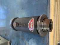
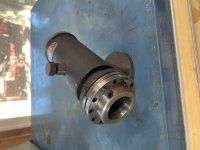
I own this, thanks to Marco.
The amount (12) of various screw positions were slightly puzzling; but it doesn't index on each hole.
There is a stiff spring behind the 'index plate', just like a large lock washer. The indexing occurs at edge of that step, created by lock washer. As it turns, that spring pushes spindle in 'Z' travel. The index plate and spring are hardened, so there is little friction and smooth rotation.
Certain this will apply to fluteless and single flute (ie M.A. Ford etc) countersinks. I built a very unsophisticated jig once, based on 1/2-20, it worked on 3/8" to 1/2" cutters.
Putting 3 more 1/4-28 screws in during tests of the action, the single step can't/ doesn't engage. The 2 work independently, #1 is a stop, 2# uses the fine threads to control 'Z' travel amount against the spring (instead of a cam) which in turn relieves cutter.
The tapped holes offer differing travel by number of degrees from stop screw. ie 1st CW from stop is full, last CW from stop is least.
Dividing Amount of Travel by Degrees of Rotation equates to relief needed on C'sinks of different diameters. Haven't worked out how to best figure what that amount is. Once I do, a formula or diameter chart will have this in regular use.
Full travel is about .100, that'd be a damn big C'sink! Running screw in can reduce to 'Z' to 0.000 movement. 28 TPI produces 0.0357 per revolution.


