What's new
What's new

Haas Kamp CP200 conversion question correct way to wire motor run capacitors on CP200 conversion.

jzr75601

Plastic
Joined
Dec 17, 2020
Hello all
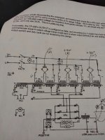
I know this is an ancient subject But I have a concern on the correct way to wire the two capacitors in the conversion. There seems to be a discrepancy between the written Step by Step instructions and the actual wiring diagram which I decided to post for all to see and compare. How do you post picture when the message "the uploaded file is too large" better yet how do you post pictures?
 
Last edited:

jzr75601

Plastic
Joined
Dec 17, 2020
Well I finally managed to get these couple pictures to post.
looking at the wiring diagram and starting at the right side of the picture the terminals are marked 1-12 with the first capacitor connected to terminal #5 and wire #9.
The second capacitor is connected to terminal #8 and wire #10 .So this arrangement doesn't seem to agree with the written instructions .any help is greatly appreciated
 

Attachments

  • RESIZED - 1.jpg
    RESIZED - 1.jpg
    587.8 KB · Views: 15
  • RESIZED - 2.jpg
    RESIZED - 2.jpg
    217.7 KB · Views: 15
Last edited:

DaveKamp

Titanium
Joined
Oct 3, 2004
Location
LeClaire, Ia
The diagram you're seeing is is correct for the unit which I was working on at that time.

Wire numbers in the step-by-step correspond to the second unit I did the conversion on, and wire enumeration varies between machines, because there's several flavors of winding arrangements. The description I used, was in reference to how that-specific-unit was configured, so when you look at your own, take into account those circumstances (and note that the factory wire enumeration for YOUR flavor is likely to be totally different from the enumeration in MY unit. Also note that the 'terminal numbers' are not a 'factory' number, they're the numbers I put on the terminal strips when I was doing my initial wiring investigation. I assigned arbitrary numbers so that I could keep track of them, you'll have to do the same with yours, and if yours has fewer or more taps of the transformer coils, you'll need to identify those accordingly.

So in short, you have to have the diagram for YOUR machine, and find the appropriate windings, determine their wire numbers, and make your connections accordingly.
 
Last edited:

jzr75601

Plastic
Joined
Dec 17, 2020
Hello again Dave, really nice to see you drop by. And really appreciate your reply.
I eventually wired the caps according to the step by step and the welder works fine what's interesting to note is the machine worked with the capacitors wired and connected the other way around as per the wiring diagram so in summary it works so that's a good thing.
I also wanted to point out in regards to the open circuit voltage, with the voltage control in the lowest setting which turns out to be 35vdc. But when welding, the voltage drops down to 15v @ 125amps welding on 16ga mild steel. Just seems to be a pretty steep slope or voltage drop from OCV to actual arc voltage . Also I find you can no longer use the little scale on the control panel as the two don't match in regards to the actual OCV. Maybe running a series of welds and recording the results might be a way to formulate a reference when looking to set up a starting point
In any event the welder performs great and it can go from welding 18ga steel @ under a 100amps to just under 300amps welding on 1/2 plate. I just find this machine and the conversion extremely interesting.


.
 
Last edited:

DaveKamp

Titanium
Joined
Oct 3, 2004
Location
LeClaire, Ia
It is called "Open Circuit Voltage", because that's what the output voltage is, when there's an OPEN CIRCUIT.

When you're welding, there's an arc, and the voltage across the arc is a function of arc resistance, series resistance (wire, leads, transformer secondary) and the voltage setpoint you've selected, and that voltage across the arc is maintained as roughly 'constant' by virtue of what is called 'slope', which is a product of the transformer's inherent reactance, and any line reactor added after.

The voltage setting you selected, is not a 'calibrated' indicator, it is simple the general reference range of what will appear across the arc when WELDING, but this will vary in actuality based on wire feed speed, wire thickness, stickout, ground lead resistance, and a bunch of other factors.

Does it weld? Does it burn hotter when you crank up the voltage? If so, it's working. Weld with it!


Top