ponderingjunkman
Cast Iron
- Joined
- Dec 9, 2003
- Location
- Cairo, NY USA
There is no wiring diagram on my Nichols mill- serial #8-G-8324. It has the switches (spindle start, red Off, coolant on/off, and forward/off/reverse) in a box mounted to the left of the saddle. Allen Bradley contactors in the box on the back.
History: Got the mill at auction this summer for 50 bucks! It had a single phase motor crudely mounted and wired, but also the original 3 phase motor in the chip pan. Put single phase power to it- the contactors worked- could hear them, but no motor spinning.
Not being too impressed with the single phase conversion, the original Master 1hp 3 phase motor was put back together into the gear reduction housing, wired directly to the motor, and ran nice and quiet on my rotary converted 3 phase (which runs the rest of the shop).
There are lots of wires in the contactor box going unknown places for the single phase conversion. I'd like to get rid of the funk, and control the spindle motor and coolant pump from the front control panel as it was originally designed.
So.... does anyone have the wiring diagram for this?
Thanks!


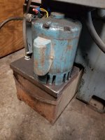
 Interesting that they generally kept the same kind of coolant scheme as the old '20's drip style though of course the modern system can provide a flood.