What's new
What's new

(Help) Teco L510 vfd - L510-101-H1 E-Stop/Rapid Stop

jhinze

Plastic
Joined
Sep 3, 2018
I have the inverter running, external forward - stop - reverse switch and pot. I'm trying to wire an E-Stop and it's working reverse of what I imagined (do I have wrong switch?)

I have an ABB CE4P-10R-02 switch from Galaco. Pull it out and it is open, push the button it's closed. Switch contactors I beleive are wired normally closed. There are 4 terminals on it.
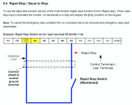
I have 03-04 set to 14, one leg of the switch is wired to common, the other leg is put into S5 terminal.

When I pull out the button, it activates the rapid stop... push it in, lets it run. I'd like it to work in reverse. Did I get the wrong switch? Is there some wiring trick I missed (I'm by no means an expert with wiring or circuits)

Any help would be appreciated..
 

rons

Diamond
Joined
Mar 5, 2009
Location
California, USA
Emergency stop contacts are open. The stop happens when the button is pressed. Contacts close.
You have to wire as normally open.
 

jhinze

Plastic
Joined
Sep 3, 2018
Emergency stop contacts are open. The stop happens when the button is pressed. Contacts close.
You have to wire as normally open.
Thanks for the reply, much appreciated. I'll see if I can figure out how to wire it normally open or get a switch that has said terminals.
 

JST

Diamond
Joined
Jun 16, 2001
Location
St Louis
Look and see if there are 4 terminals. If so, odds are two are NC and two are NO.
 

rons

Diamond
Joined
Mar 5, 2009
Location
California, USA
The switch blocks I use
Emergency stop contacts are open. The stop happens when the button is pressed. Contacts close.
You have to wire as normally open.
It is opposite. On schematics the start contacts are NO and the stop contacts are NC. Sorry.
Just look at any drawings in your drive manual. Should be easy to see which way the wiring goes.

On pages 4-33, 4-34 the stop switch is NC.
Follow the picture on 4-34 for 3-wire control.
 
Last edited:

motoxsgb

Plastic
Joined
May 3, 2020
I can understand the confusion on this. Traditional E-Stop circuits are maintained. Reason for this is if a wire pulls out of a terminal, or something else fails there is no way to determine this (except for an E-Stop button test). So the design of this VFD relying on a [true] input for an emergency condition, instead of the "normal" state being energized is in my opinion a design flaw (deviation from typical industry best practices).
 

mksj

Cast Iron
Joined
Aug 10, 2010
Location
Tucson, AZ
I normally would use both a NC AND NO, COM/+12V come in to the E-Stop switch and parallel to the inputs of the NC and NO switch blocks. NC then connects to your run inputs S1, S2, and S3 for 3 wire; the NO switch block is connected to say input 5 programmed for (14) Rapid Stop (Decel to stop). When you push the E-Stop it disconnects all the run commands and issues a rapid stop command. Once initiated rapid stop also requires all run commands to be removed to reset/remove, as it could be dangerous if you reset the E-Stop and you had an active run command in 2 wire control. All run commands should be run through a NC E-Stop contact so if there is any switch or electrical failure (latched power relay) would result in a run command not be executed. E-Stop systems usually have some form of redundancy as well as more elaborate types require some form of closed loop verification of function. The Teco L510 does not have provisions for an external braking resistor and not sure if it has the ability to prevent an over voltage error if to rapid a stop. In some cases where their is very high inertia and the VFD can not dissipate the voltage quick enough they will trip into a free run mode with an over voltage error, some will modulate the braking rate to prevent this.

1673630629886.png


Top