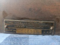
Here's the pics. The third photos has a series of lines that appear to be about 1" machining marks along the long axis of the plate.
Back in the UK there were lots of "marking out tables" built like this.
The surface was machined on a planer with a flat tool, cocked over a little, to get these lines on the surface. As the table was used it was easy to see the wear as the lines would "widen".
This little anecdote might be interesting.....
I remember, as an apprentice, being in the forge and watching how a crankshaft hammer die was made. They'd start with a block of tool steel maybe 24" long, 12" wide, maybe 16" high. First job was to cut a tapered dovetail about 2" deep, on one of the 12x24 faces. This was used to hold the die in the steam hammer (type FB !).
The other 12x24 face was cleaned up and the edges squared.
The die block was then craned onto the marking out table, where the face was blued, and the shape of the die cavity was marked out using squares and a height gauge.
Then the edge profile was clearly identified by going around and using a small center punch to mark out the full perimeter.
Then on to the manual die sinking mill, with tapered ball endmills the toolmaker would dig out the cavity using a bunch of templates to get the depths and profiles.
Then the finisher would use a hammer and small chisels to round over all the edges, then finish with a die grinder.
All really skilled manual jobs.
After several thousand cranks, the top 3" or so of the die was machined off, and the process repeated.
Hopefully of interest
Bob


