What's new
What's new

New feed nut bore location?

Hbjj

Cast Iron
Joined
Mar 18, 2013
Location
Washington st
I'm ready to thread a new cross feed nut for a lathe and I'm wondering how a pro rebuilder would go about finding the location of the screw in the new nut?

This lathe has a taper attachment and a removable thrust bearing block.
 

Attachments

  • 20230103_120616.jpg
    20230103_120616.jpg
    820.2 KB · Views: 16

J_R_Thiele

Stainless
Joined
Jan 22, 2003
Location
Columbia Missouri
Not a pro rebuilder- but I do have a copy of Connellys book and recently read on this.

I do have some questions. Do you have a new leadscrew for the new nut- or will it be a new nut on the existing screw? Do you still have the old nut? Do you plan on doing any scraping or other work on the carriage?
 

Hbjj

Cast Iron
Joined
Mar 18, 2013
Location
Washington st
I made a new screw

Old nut and screw are very worn

I revealed the center of the cross slide and gib a bit and fit the gib a little but I have no plate here so it was all blind if you know what I mean

There is significant wear on the cross slide...it has surely moved from the factory position so trying to measure the old nut is going to result error.

I have done this job a few times and it worked ok but it would be helpful to have concisely worded step by step description.
 

jim rozen

Diamond
Joined
Feb 26, 2004
Location
peekskill, NY
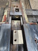
Wear means the centerline of the screw in the slide moves, in two directions. It moves sideways, towards the fixed side of the slide (away from the gib, which is effectively getting 'wider' and it moves "down" as the flat
ways on the slide get 'thinner.' My approach on the few times I've done this, is to move the slide to the front, with the screw and bushing removed, so you can visualize the new nut blank or the hole for it, depending on the construction, and then scribe the blank carefully through the bushing hole. Helps to blue the nut blank. You can also make up a specialized punch, that just fits inside the threaded bushing hole on the apron, to go in there and punch the location. If the nut is going in a hole then some careful measurements with a pin in the slide, compared to the hole in the apron, can give you real numbers.

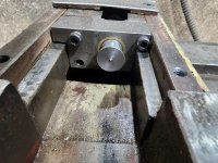
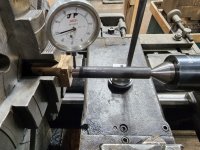
In my case the wear on the slide was extreme which meant a new gib, re-machined and scraped slides, and a new nut. The hole had to be enlarged a lot by boring to get it on center again. Remember that a certain amount of misalignment can be tolerated when the slide is mid-span, but getting it to within 5 thou of center-to-center is a good shot at it.
 

Richard King

Diamond
Joined
Jul 12, 2005
Location
Cottage Grove, MN 55016
I'm a pro, but I am having issues understanding your picture and writing. What is the slide in the top of the picture, part of the taper attachment. What brand and model machine is it, so I can find a blue print on Vintage machinery. Can you show the cross slide. It looks like your ways are shot and dirty.
 

Hbjj

Cast Iron
Joined
Mar 18, 2013
Location
Washington st
I went with the transfer punch in the thrust bearing bore
 

Attachments

  • 20230104_064645.jpg
    20230104_064645.jpg
    672.9 KB · Views: 7
  • 20230104_064712.jpg
    20230104_064712.jpg
    765.4 KB · Views: 7

Richard King

Diamond
Joined
Jul 12, 2005
Location
Cottage Grove, MN 55016
Thank You for the info. Over the years I too have only done this a few times too. I did on rebuilds of Hardinge and Warner Swasey Lathes. Your TurnMaster is a copy of a Clausing and I have linked to a Vintagemachinery.com reprint of a Clausing Lathe that looks like your machine. http://vintagemachinery.org/pubs/182/25332.pdf on Page 13 fig. 14 - Page 16 fig 24 shows a picture of the cross-slide or Crossfeed, Then on Page 18 fig 26 is about lube, but it shows the cross-feed nut and cross feed slide in some detail. Then Page 20 shows a breakdown of the saddle assembly and a page in the back with no number on the Taper Turner assembly.

I always like to do this way of explanation with drawing to make it easier for the other readers to understand what's going on as I bet there are hundreds of the members reading this too.

With the wear in the saddle top and cross-feed I think your measuring from the wrong end. The taper attachment is hardly worn compared to the cross feed or operators side of the slide.

I used to rebuild a lot of Hardinge lathes plus did service calls for the Minneapolis local dealer The Gramquist Company. Hardinge had a special kit they would send us and other maintenance techs / rebuilders. It had a steel drill bushing that slid in the crossfeed hole or "Keep bracket" Clausing manual page 20 part 55230 and Hardinge's instructions that came in the kit had us bolt in the new nut block on the under-side of the saddle. Then they had a long center drill that fit inside the drill bushing to spot drill the bronze nut, then they send a tap drill and acme tap that we tapped the nut inside the machine.

Your way is using the original taper turning centerline location and not the worn ways location. Your way looks good if you were installing Turcite on the saddle and gibs to get it back to the original centerline. Your way as Jim said you will need to have more side clearance in the thread or it will bind up near the operators side when you crank toward the operator.

If I were doing it I would turn a drill bushing out of steel or bronze to fit into the saddle clearance hole and make a spot drill and pully (long drill) drill the bronze nut in the machine and not on a lathe. Then put it in your lathe, center the hole and turn the acme thread. That way it will be centered on the worn way.

I would never have done it that way as I always was rebuilding / scraping the ways.
 
Last edited:

Richard King

Diamond
Joined
Jul 12, 2005
Location
Cottage Grove, MN 55016
To the readers look at the photo where he has the nut in his lathe that he is indicating. Look at the way behind that set-up. That way shows a long raised line on the ways. The saddle bottom that runs on that way has a straight oil groove cut into it. Many of those old copied lathes build in Taiwan made that mistake. I see it on machines coming from China now. They should have cut a diagonal oil groove so it would wear evenly. American made Axelson lathes and other old designs made the same mistake. Now with CNC mills the builders can program diagonal oil grooves.
 

Hbjj

Cast Iron
Joined
Mar 18, 2013
Location
Washington st
I'm all done and it's back in service

Huge improvement over what I started with

But it does get a little tight at the back of the travel...

I may try again later but first I need to find or build a proper follower rest for this lathe

Thanks


Top