What's new
What's new

Confused re spindle alignment - BS #2 grinder rebuild

StrayAlien

Cast Iron
Joined
Aug 18, 2014
Location
Melbourne, Australia
Hi all,

I am at the point of beginning the spindle remake and bearing refresh on a 1928 Brown and Sharpe #2 grinder.

This guy:

http://www.practicalmachinist.com/v...inder-early-spindle-advice-dimensions-325875/

Yes, it is a complete basket case but, despite what the 'before' pics show, it is coming along nicely:

IMAG1842.jpg

The straight-shaft spindle is held in two tapered bronze 'box' bearings at either end of the spindle block. The bearings are keyed are held in place by tightening collars that have a 'differential' thread mechanism to pull the bearings into their tapers.

I plan to line-bore the bearings in-place, lap them, and then create a new spindle to suit and lap it to fit.

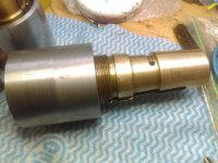
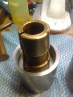
To line bore the bearings I have created 'boring caps' that fit on each end of the spindle block. The front bearing is held in place by the stock tightening collar with my boring cap attached external to it, the rear boring cap has the 'differential' thread mechanism on it to push the bearing into the taper.

Both caps have a bore hole in them to hold the boring bar. Bore to bar clearance is about 0.0002". The bore in the caps are both longer than 1".

IMAG1951.jpgIMAG1975.jpgIMAG1978.jpg

The threads in the boring caps are an excellent fit on each end of the head with almost no play. The boring bar goes through one cap and then through to the other like a dream and rotates beautifully - even with 1" long bores at 0.0002" clearance 17" apart - so they are pretty well aligned I'd say (?). The boring bar rotates with zero movement, and with it in place if I unscrew either of the caps with the bar mic'ed, there is hardly any movement on the bar. So caps, bore, threads seem pretty concentric.

My confusion is this:

The boring bar, when in place (like the third pic above) is not in the same plane as the flaked reference surface you can see (near-side surface of the block).

On a surface place with that flaked surface resting good parallels and the boring bar and caps in place there is about 0.015" height difference between the boring bar at each end (measured just outside each cap - about 18" or so apart). Connolly says the limit is 0.0003".

If I flip it over and rest it on the other bearing surfaces the height difference changes ends. Both bearing surfaces seem to be in the same plane as does the gibs ways:

... but on the same setup the factory-machined bases of the spindle cap threads are about 0.006" out. The differ in OD by about 0.001".

.IMAG1989.jpg

I am trying to figure if I have something wrong. Even without my boring caps etc etc, factory-machined bases of the spindle cap threads are not in the same plane as the bearing surfaces or the flaked 'referenced surface' (which actually is in the same plane as the bearing surfaces)

Have I got it wrong or missed something?

All help and advice appreciated.

Greg.
 

Richard King

Diamond
Joined
Jul 12, 2005
Location
Cottage Grove, MN 55016
A few more pictures would help. I have just been reading and looking at this amazing site: http://www.vintagemachinery.org/pubs/2185/16325.pdf That helped me remember working on a few of these machines 40+ years ago.

It's hard to believe the factory got it wrong,but I have seen that happen a a few times or some other repairman was in there once before and screwed it up.

As a scraper I am looking at this in another perspective. I had a discussion about squareness or saddle and table and then squareness to the spindle sweep to the table travel and vertical rise of the column. Brown & Sharpe would have made it square when new because they had no idea what the customer was going to use it for. Unless it was a special order I suppose. When a customer had me-scrape a surface grinder I always asked them are you going to grind slots? 90% of them said "no I am only going to grind flat surfaces, never slots" In that case I never squared the saddle and table and swept the spindle to be square and parallel those travels. I don't want to get in a debate with anyone now about how right and wrong that is. Trying to help here.

Now as a scraper we have a rule we follow. "If it's a fixed spindle machine and the spindle can not be scraped for adjustment after your discover errors in scraping of saddle and table. (An example is a Horizontal Mill with spindle bore is in the machine casting.) and if the spindle head is removable or separate you start at the longest slide be it the base or saddle in your case and then match fit it to the shorter member like the top of base, then scrape the table , match fit it to the saddle, squaring them to each other (in the new machine builders case) then scrape column square to table top, mount spindle head in column and match fit the ways and sweep square to column 4 ways, then check if it is square to the table/saddle squareness. A real pain if your a new machine builder or if your a rebuilder and your customer is going to grind slots.

The last operation B&S did was sweep the spindle to the table travel and if it was not square they scraped the head ways to make it right. As it is a removeable head and it's a lot easier to scrape it then starting at the base and making them square to the head. How is the table and saddle ways? If they are good be a detective and mount a mag bad on the table and test the parallelism of the travel to the column flats. Then if you have a good machinist blade square (+/-) .0001"/ 12" and rest it on the column flat in both directions, side to side and vertical rise and move the saddle in and out. That should be .0002/12"or better on side to side and Plus on operator side on vertical rise .0005 to .0008"/12" to compensate for sage and ware.

So your tests may have happened if the head was not bored straight from the factory and the scraper hand had to scrape it that way to get it to pass inspection. Or someone else was in there and didn't care because they were only going to grind flatness because when you grind the table top and chuck it doesn't matter. As it is a single point spot the grinding wheel hits when grinding.

Another thing is have you mic'ed the flanges or caps to be sure they are the same OD (sorry had to ask) and did you stone the surfaces the parallels are on. Remember your dealing with multiple error. A small ding of .002" under the parallel could multiply out on one end .006". G-Day :-) Rich

Added: 11/15 945PM CST:

On Page 34 you can see the column bolts to the base. I highly doubt the factory scraped the column back there to align the spindle, but I can see it happening by some other rebuilder or a F Up at the factory. You should check the squareness of the table and saddle like you would on a Mill and if that is square and you do the tests with a blade square as I mentioned before those results would be interesting to know. Also MachTool (Phil) is a super rebuilder and scraping teacher. RC99 (Rich) If you are close one of them I bet they would have the square if you don't have one. I was thinking you should down load a copy of
https://www.scribd.com/document/107621833/Testing-Machine-Tools-Dr-Schlesinger as it has the new machne spec's in it.
:-) G-Night. Rich
 
Last edited:

AlexO

Banned
Joined
Sep 12, 2004
Location
RSA
I am trying to figure if I have something wrong. Even without my boring caps etc etc, factory-machined bases of the spindle cap threads are not in the same plane as the bearing surfaces or the flaked 'referenced surface' (which actually is in the same plane as the bearing surfaces)

Have I got it wrong or missed something?

All help and advice appreciated.

Greg.

Shot in the dark : they might not be same diameter ??
 

Richard King

Diamond
Joined
Jul 12, 2005
Location
Cottage Grove, MN 55016
I was thinking your set up looks good to bore the hole. How are you planning of on powering it and feeding it in? Are you going to do a You Tube show? That would be cool if you did. If you plan on only grinding flat surfaces. By dressing the wheel is all you need to do. It's not a boring machine where that alignment would be important. Rich
 

StrayAlien

Cast Iron
Joined
Aug 18, 2014
Location
Melbourne, Australia
Rich, Alex. Thanks.

Apols for the 24hrs-later reply. This time difference eh!

First thing: the OD of the flanges are about 0.001" different. I did check that :-)

Second thing: g'day! :-) re vintagemachinery.org - it was me that uploaded that manual there. :-) and I have Schlesinnger too.

Third: Phil has kind of evaporated. We agreed if I could get the numbers for a scraping course (which I did) he'd do it - but things seem to have changed. Also, RC99 is about 2000km away by road. :-)

Rich, second post first. Thanks for the comment re the boring set up. Excellent - for a newb like me that is pretty inspiring. It may be a bit low-tech but I am aiming to try to get the spindle rebuild without going silly. By boring it I am aiming to clean up the bearings and get front/rear aligned. Not looking for a pefect finish when boring as I'll lap them.

I'll post pics here as I go, but I'm not quite a you-tube vid maker kind of guy - yet!

I understand the bronze on these bearings is pretty hard stuff, so I'll be grinding a kind of 'shear' bit with some positive rake and taking small cuts. At this point, I reckon I'll just power the bar by a low-speed hand drill with a flexible shaft attached to the bar. I'll shorten the bar to suit when the time comes, but that is also one of the reasons for having more than 1" of bore in each cap - to keep things steady with a not-so-amazing power feed.

Re 'slots vs flat surfaces' I reckon I have a use or three for cleaning up some dovetails and also the lathe carriage v-ways. So, I guess not just flat surfaces.

Onto alignment:

Thank you for the advice. Detailed as usual and delivered with the love and passion for this work that you radiate. Thank you. You're an inspriation.

I will undertake your instructions to get some insight into whatever else might be going on. I'll re-do my head measurements, but I'm pretty sure they're ballpark okay. I 'Connolly burr file'd most things before measurement. Prefer that to a stone - though I have the stone from McMast carr you recommend.

I'll also remount the head just to see if the boring bar is actually near the planes it is supposed to be when mounted. I'll have all weekend to confuse myself!

Re pics: I only get 5 per post by I'll lob some more here and in a following post as well.

This is what I started with (the carriage was under a layer of grass) - it has been disassembled and left outside for 10 years or so. The body was left in a barn - so thankfully it go no rain - but it was near the open door, so not great.

IMAG0111.jpg

This is the spindle as found:

IMAG0147.jpg

It did all eventually clean up, but spindle play in bearing was about 0.020". Yep. 20,000 times greater than it should be. Much of the machine has been like that, but the lower half is almost all functional again. No scraping done yet - just getting it functioning is the first step.

So many things were bent and worn to crazy amounts. It is hard to believe it still ran. This is typical:

IMAG0488.jpg

And with so much spindle play people have been tightening things ridiculously:

IMAG1886.jpgIMAG1889.jpg

Continued ...
 

StrayAlien

Cast Iron
Joined
Aug 18, 2014
Location
Melbourne, Australia
Re the spindle and head refresh:

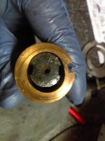
The two caps I have created are to help bore the bearings in-place. The front cap screws onto the bearing threads outside the stock collar and the rear cap replaces the collar to screw onto the head and bearing at the same time. Note rear bearing is missing a phenolic spacer - I suspect to help it close up when tightened. I'll make a new one:

IMAG1971.jpgIMAG1969.jpg

Both bearings have wear in them like (with the rear being a bit ovalled):

IMAG1917.jpg

The rear probably needs about 0.010" bored, and the front might only need 0.005".

The base of the head block gives enough space to adjust a boring bit and get some idea of what is going on during boring:

IMAG1986.jpg


So, all pretty nasty really. But, not beyond saving. In case anybody is wondering why? It is the journey, not the destination here. I'm learning a lot as a go - and for this old girl it was me or the scrappers. Can't let happen now can we.

I'll do the RK measurements as best I can and report back here with pics.

Many thanks,

Greg.

PS Richard, was there some specific pictures you were interested in?
 

Richard King

Diamond
Joined
Jul 12, 2005
Location
Cottage Grove, MN 55016
You tuber Brian Brooks (I think thats his last name, sorry) brought a tilt table to the GA class and it was a mess as far as alignment. I told them about a job I did way back when that another rebuilder did and totally screwed up a Mono-Set T&C grinder. Normally we can play detective and take measurements of the clearance surfaces that the factory milled at the same set-up when they milled the ways surfaces. But this lousy rebuilder milled those too and we had no way to reference the ways. The machines geometry was so bad that when you moved the 6 axis's (there are 7 but one is a swivel mounted on a Timken Bearing)they got tight on one end or another. A real headache. What I did is what I told Brian to do. Use the feed screws or shafts to set on a plate and milling machine to measure to get alignment so you can mill it straight again. Your one picture shows your boring bar. I would use it to test to be sure the outer caps are parallel to the scraped surfaces or flaked ones you mentioned. That way you have something that can't be adjusted(moved) and it has is original to the screw threads(caps) that look accurate and were done at the factory. I love how excellent your work is. Bringing that machine back is amazing and you should get an award. As you will when you do your first grind.

As I read you saying your going to hand feed the boring bar and then lap the bushings I cringed as please don't use a carborumdom lapping compound like Clover to lap it. Order some Timesavers lapping compound yellow as it won't charge into the bronze.

Also use your imagination and make a long lever to push the boring bar (like they have on turret rams on turret lathes) or mount it on the table of your mill (assuming you have one) and fix the housing to the spindle housing to some how and use the table feed. Or a simpler way would be to mount it in a lathe and make some sort of fixture on the cross slide to hold the housing and feed it either from that and chuck the bar up and use the lathe spindle to turn it.

It's a small world isn't it, you sending that manual to Keith. When I return from Europe I am going to start to send my collection of sales, parts and maintenance manuals to him too. If I don't do that someday they might get buried in a landfill after I pass. G-day...:-) Rich
 

StrayAlien

Cast Iron
Joined
Aug 18, 2014
Location
Melbourne, Australia
Thanks Richard - I have seen the vid on the GA class table. :-)

Re lapping - Some Brownells 600 grit garnet-based lapping compound arrived yesterday - the garnet compounds are not embedding. Timesaver is also garnet based. So - no nasty stuff hitting the bronze. :-)

I'll consider the 'long boring bar' thing. Thanks.

On your comment "I would use it to test to be sure the outer caps are parallel to the scraped surfaces or flaked ones you mentioned." Unless I misread you there - this is exactly what my confusion is about - the 'flanges' and threads are not parallel with the scraped surface. The gibs, scraped surface, and the opposing bearings on the head all seem in the same plane, but the machined flanges and thread seem not to be in that plane. I'll be re-doing measurements this weekend to confirm. I am hoping I am wrong!

To both you and TGTool for your comments on the work done so far. Thank you - it means a lot to me for guys like you to say that. I am pretty new at this - it ain't my day job.

Thanks again,

Greg.
 

Richard King

Diamond
Joined
Jul 12, 2005
Location
Cottage Grove, MN 55016
Like I said that spindle axis should be square and parallel to the saddle and table axis So until you can test that better not do anything to the ways being out of alignment. A whole lot easier to move or scrape the spindle head then the saddle and table. In the ideal perfect world, the spindle and those ways would be on the same plane 360 degree sweep all 4 corners (co-planer, right Dee? lol. Do you have a steel, granite or cast iron parallel? I see You have the machine saddle and table assembled? Can you crank the table back and forth? If you can lay the parallel on top of the table and indicate it parallel to the travel of the table ways.

With slight pressure use the table T nuts to tighten it down. If you can hang the head on the vertical feed screw put the head in the column and tighten the hold-downs and gibs. Leave your .0001" boring bar in the spindle bearings caps. Then use a clamp in indicator like you use on a milling machine and sweep the parallel face say in 12". That would prove the head ways were scraped to sweep the table axis. If you have a angle plate iron like Russ scraped on that same KR you tube or a granite square of a blade square. Set that on the table face to the column and indicate the that face of the block and use plastic shim the face parallel to the vertical travel. Then sweep the spindle to that angle plate. It will also have to indicate the face parallel yo the table travel too.

Or just bore and lap you bronze bushings and finish the spindle and use that to do the sweeping after it's finished. I'll write Keith Rucker and see if he can do a You Tube showing these tests on his channel. A lot easier to explain then trying to type it here. The class before this one we checked his machine and it's like new.

So your planning on grinding slots? ...this is fun...but your doing all the work and have all the headaches, ...lol Rich
 

StrayAlien

Cast Iron
Joined
Aug 18, 2014
Location
Melbourne, Australia
Thanks Rich,

Np with 'hard to explain' - I understand what you've said. Thanks.

I've not got a granite parallel yet though I have one on order (a granite tri-square actually). I'll try the angle plate method.

The table and carriage do now crank (after quite some work!) so we're good to go. :-) I doubt we'll get the same fine result as with Keith's. This old girl likely saw heavy use in WWII and then it was downhill from there I'd say.

Re slots: I guess I don't want to limit the work it can do so am happy to put in the effort to get it back into 'general use' shape. My intention is to use it to help better some of the other machines - like the poor tired old 1941 SB 10" lathe, and I guess that means dovetails and vways.

Time to start. Thanks again.

Greg.
 

StrayAlien

Cast Iron
Joined
Aug 18, 2014
Location
Melbourne, Australia
Reporting some findings:

I only get max 5 pics per post here so this might go across a few posts.

I re-cleaned stuff and burr-filed surfaces and rested the head again on the 'reference' scraped surface.

IMAG1992.jpg

The two bearings on the opposite side of the head were within a couple of tenths and in the same plane - so the reference surface matches the bearings. Cool.

IMAG1993.jpgIMAG1994.jpg

Those measurements are about 5" apart. But .. rechecking the flanges (8.5" apart) gives

IMAG1996.jpg

It's low at the front. Taking 0.0005" off for the diff in OD gives about 0.0065" difference on the flanges.

Continued ...
 

StrayAlien

Cast Iron
Joined
Aug 18, 2014
Location
Melbourne, Australia
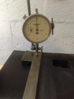
Measuring the boring bar just outside the caps (approx 17" apart) shows about 0.012" diff.

IMAG2002.jpg

Given the bar measuring distance is twice the flange measuring distance and the error is about twice I'd say that means the bar is in the same plane as the flanges .. but neither is aligned with the 'reference' surface.

I remounted the head on the machine, and with the bar and caps in place and did some tests. I was not aiming for meauring perfection, just more information.

First test shows the bar leaning right (looking from the front) about 0.001" in 4". The is the direction one would expect based on the previous measurements.

IMAG2021.jpg

Next, following Richard's recommended tests:

I aligned an angle plate to be parallel with the table travel (to within a tenth or so) and performed a swing-around test with an indicator on the spindle - I don't have facilities to mount my 0.01mm indicator there, so the trusty 196 0.001" is used.

Setup looked like this:

IMAG2029.jpg

and the results were pretty good - as near as dammit bang on:

IMAG2030.jpgIMAG2028.jpg

So I figure this means bar rotates in line with the table movement. Nice. Though, it is possible the carriage ways have some small misalignment to the spindle.

Continued ....
 

StrayAlien

Cast Iron
Joined
Aug 18, 2014
Location
Melbourne, Australia
The same test vertically showed nothing unexpected - a large droop. The lower front bearing surfaces on the head are pretty worn. In the pic below I had zeroed the indicator at the lower point of the 'swing around'. So it is showing 0.008" there.


IMAG2033.jpg


The good thing is that over a 6" movement vertically, the head-to-angle-plate movement was only about 0.001". Happy with that - I am figuring that mean the bar droop comes from the head bearings and not the column ways. Cool. It also means the above figure is actually 0.007" droop. :-)

I also believe column ways are all original and have not been re-ground or redone at any stage. I judge that from the way the that paint and primer rides around the edges of stuff.

I'll do some more tests tomorrow - specifically with a square on the column ways. I kind of ran out of time today.

Thanks again all, and thank you Richard - I learned a great deal doing these tests.

Greg.
 

Richard King

Diamond
Joined
Jul 12, 2005
Location
Cottage Grove, MN 55016
A couple of more tips. Your angleblock is not super precision as you know. Also when testing the head dip, use plastic shim stock or metal shimstock to put under the worn area to get the correct amount you would scrape off the other side as you are getting multiple error in a test like that. At least now you know and will have confidence. As stated. I don't guess on answers as i
I P1P2give 50 years experience. I would proceed with your plan on spindle and then test your a angle plate. .0002"/ 12". Then scrape head. Your welcome. Rich


Top