What's new
What's new

10EE KB 255D drive problems; Parker 514/507 conversion questions

DAN Z

Aluminum
Joined
Mar 18, 2005
Location
RI
I believe I have read just about all the threads to this conversion.

I have 1942 round dial 10EE. When I bought it the guts were gone and it was setup with a KB control 225D (9391) 230vac input 180vdc output. I have been running with this controller for many frustrating years.

On a good day, going downhill, with the wind to my back, I can get 1,250 rpm. So says the dial tach. I forget it’s been a while, but I think the field winding is running though the original potentiometer on the base. That’s what gets me a little above 1000rpm. I am very interested in this conversion. I have the 3HP Reliance large frame DC motor. I have been studying the Parker/Eurotherm 514C/507 4Q SSD DC Retrofit into 1961 10EE modular wiring schematic drawn: MES. I do not have the ESLR control setup. I would think I would activate the original drum switch by the headstock.

So, my questions, which are many; has anyone repower this motor with this setup? My power source is 208vac 1ph. What do I need to do to boost my Voltage to 330vac? I do not have the “T5 plus boost transformer”.

I can manage electrician, but not electrical engineer. Any help would be greatly appreciated.

Dan
 

Cal Haines

Diamond
Joined
Sep 19, 2002
Location
Tucson, AZ
hitandmiss (Bill) is running a modified KB drive and (AFIK) is happy with it. Start a conversation with him and he can probably help you out.

How is it that you have 208 single-phase power? Most residential power is 240.
 

Hobby Racer

Aluminum
Joined
Apr 18, 2015
I can probably help you out here. I Just recently converted my 42 round dial 10ee using a 514C. Like you I used the original 3hp large frame motor and the original potentiometers and no ELSR, basically your exact setup. I tested many input voltages and in the end chose to use my 240V 1ph mains input directly into the 514C. I found no need to boost the input voltage and I achieve a max rpm of 3250.

I use all the original machine controls and it operates flawlessly. The setup can be very simple or quite complex depending on how you want to set it up. If your looking for the same functionality as the original drive system, the setup is quite simple.

To echo what Cal asked, do you really have 208V or do you have 240V?
 

hitandmiss

Titanium
Joined
Jul 31, 2010
Location
Rochester, NY USA
Hi,
Cal has asked me to jump in.
Many questions need to be answered.
Do you really have 208 Volt power?
What is the motor field voltage at max RPM?
Is your Tach. reading correctly, many read low, some very low.
What is the pulley size on the motor and spindle?

This is a retrofit I did some years ago with full docs.

43 10ee MG with Parker 514c-16 DC Controller

Bill
 
Last edited:

hitandmiss

Titanium
Joined
Jul 31, 2010
Location
Rochester, NY USA
I was going to let him answer some of the questions first.

The vagueness quoted below needs to be ironed out.

"On a good day, going downhill, with the wind to my back, I can get 1,250 rpm. So says the dial tach. I forget it’s been a while, but I think the field winding is running though the original potentiometer on the base. That’s what gets me a little above 1000rpm."
 

DAN Z

Aluminum
Joined
Mar 18, 2005
Location
RI
Hi Bill,
I hope to get you some answers this evening. I am on East coast time. The time stamps seem to be off. It's 4:00 pm now.
Dan
 

DAN Z

Aluminum
Joined
Mar 18, 2005
Location
RI
Hi Bill,
242vac line in.
My dial tac, and my strobe tac are very close.
My motor pulley is 6.75", and my spindle pulley is 7"
(2) vee belts
As to the question; what is the field voltage, where do you want me to take the reading?
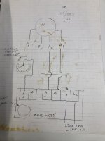
Not sure if you can see this well, but this is my current configuration. This was how this was wired when I bought the lathe.
Thank you for your time.
Dan
10EE kb schematic.jpg
 

DAN Z

Aluminum
Joined
Mar 18, 2005
Location
RI
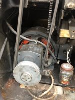
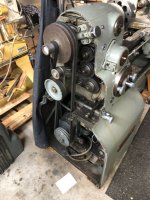
Here are a few more picture.
 

Attachments

  • reisotate.jpg
    reisotate.jpg
    57 KB · Views: 63
  • 10ee motor.jpg
    10ee motor.jpg
    172 KB · Views: 12
  • IMG_9446.JPG
    IMG_9446.JPG
    146.1 KB · Views: 11

Cal Haines

Diamond
Joined
Sep 19, 2002
Location
Tucson, AZ
The field voltage is the DC voltage between motor leads F1 and F2 or between terminals L1 to F+. We need that reading with the KB drive dialed up to maximum and the field rheostat turned all the way down and all the way up.

What controls the KB drive itself?
Correction:
We need the voltage between motor leads F1 and F2 or between motor lead F1 and KB terminal L1. According to your diagram, one of the two wires that connects to the bottom of the rheostat is motor lead F1; the other connects the KB terminal F+. You can identify the F+ lead by looking for a 0 Ohms reading between the rheostat leads and KB terminal F+. Once you identify it, label it F+ and the other rheostat lead F1. The you can then measure the field DC voltage between rheostat terminal F1 and KB terminal L1.

On the diagram, what is the text leading to the circle in the lower-right corner of the KBPC-225?
 

DAN Z

Aluminum
Joined
Mar 18, 2005
Location
RI
The circle is just the symbol for the speed control knob on the KB.
I did take reading as first asked, but what you would like me to do is to take a reading before the rheostat and the line in, correct? which is the same as F1 and F2. do you still want me to put the rheostat though its paces?
Dan
 

Cal Haines

Diamond
Joined
Sep 19, 2002
Location
Tucson, AZ
Yes. Speed control knob on the KB at maximum. F1 to F2 voltage with the speed control knob for the big rheostat all the way down and all the way up. Need DC voltages across F1 and F2 and corresponding spindle speeds.
 

DAN Z

Aluminum
Joined
Mar 18, 2005
Location
RI
Update:
KB speed control max 100%. Voltage between F1 and F2 ~131 VDC rheostat at lowest position, no load 850rpm.
Rheostat at max position; voltage fluctuated between 96-104 VDC no load rpm1500
 

Cal Haines

Diamond
Joined
Sep 19, 2002
Location
Tucson, AZ
You're not getting much weakening of the field. Normally the field voltage will drop down to about 40 VDC when fully weakened.

Bill will know for sure, but it looks like the KB is wired up to provide half-wave rectified 240 AC to the field. Rather than a nice, even field voltage, your field is switching on and off 60 times a second. A dedicated, full wave rectifier might give better results. There are also some adjustable speed controllers on Amazon that work from 240 VAC and can be used with a bridge rectifier, and perhaps a capacitor, to provide a better field voltage supply.

Using your strobe tachometer, what do you read for motor speed with the KB drive turned all the way up and the big rheostat turned all the way down? (That should be the "base speed" condition, where you have full armature and field voltage.) At base speed, the spindle motor should be turning a 690 RPM.
 

DAN Z

Aluminum
Joined
Mar 18, 2005
Location
RI
I will get you that reading before the day is out. I thought the biggest problem with these KB drives is that the output is 180vdc and these motors are wound for 230vdc
Dz
 

Cal Haines

Diamond
Joined
Sep 19, 2002
Location
Tucson, AZ
I think that's true of all DC drives operating from 240 VAC. That's why a transformer is often used to boost the input voltage to the drive. If I understand what Bill told me, he was able to do just that with his KB drive. He'll have to supply the details.
 

Hobby Racer

Aluminum
Joined
Apr 18, 2015
I think that's true of all DC drives operating from 240 VAC. That's why a transformer is often used to boost the input voltage to the drive. If I understand what Bill told me, he was able to do just that with his KB drive. He'll have to supply the details.
I get a measurement of 240VDC (when adjusted properly) out of my 514C with only my 240VAC mains as input to the drive (BTW my mains actually measure out at 245VAC)? I understand there are losses in the AC->DC conversion but since the VAC value is the representation of the equivalent DC power dissipation, shouldn't a full wave rectifier be able to achieve an equivalent DC output close the to input AC value, minus any electrical losses?


Top