What's new
What's new

1949 10ee Trouble Shooting? (WiaD tube drive)

zgoo

Hot Rolled
Joined
Dec 10, 2002
Location
Portland, Oregon
I have a 1949 10EE that has been in storage for 25 years. My shop have a wild leg three phase power and is there an order in which the wild leg needs to be connected? When I plugged it in the transformer hums, and the two large tubes get warm and a couple of others small tunes light up a bit, but nothing will run. There is a push pull switch with a key switch above it and they do nothing, like turn the machine on or off. Any help with where to start?
 

rke[pler

Diamond
Joined
Feb 19, 2002
Location
Peralta, NM USA
L1 and L2 should be the supply legs to a WiaD drive, you might want to track the power in the rear contactor to be sure as a lathe supplied with a coolant pump will have wanted all 3 legs supplied.
 

Cal Haines

Diamond
Joined
Sep 19, 2002
Location
Tucson, AZ
That confirms that it's a Work in a Drawer (WiaD) drive. There aren't very many of those still in service. But there are people here that can help you get yours running.
 

zgoo

Hot Rolled
Joined
Dec 10, 2002
Location
Portland, Oregon
The power comes in the back of the machine by the headstock. Where is the terminals L1 and L2 located. What about the keyed switch and push pull switch on the lower front near your knees on the left? They dob't seem to do anything?
 

zgoo

Hot Rolled
Joined
Dec 10, 2002
Location
Portland, Oregon
So I which the legs so the wild leg was not on L1 or L2. So the push button on off switch still does nothing that is on the lower front of the machine. On the back of the headstock I removed the cover that has a small brown switch sticking out of the cover. Inside the cover is the brown switch that looks like a barrel switch. It doesn't seem to do anything. There is also a large contactor that is open and not ingaged. But if I manually ingage it the lathe will run. Any help with troubleshooting this?
 

Jdub63

Aluminum
Joined
Jan 10, 2020
I would check the start push button on the front, then check the coil and the heaters on the contactor. There may be two switches on the back cover, one is a reset for the contactor, the other might be a on off for the coolant pump. The coolant pump only gets power when the contactor is closed.
 

Cal Haines

Diamond
Joined
Sep 19, 2002
Location
Tucson, AZ
I don't claim to know much about WiaD drives, but I think it may use the same Allen-Bradley AC contactor (aka motor starter) that the motor/generator machines use. If so, this thread explains how it works:
If you have something else, please post a photo.
 

zgoo

Hot Rolled
Joined
Dec 10, 2002
Location
Portland, Oregon
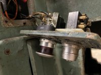
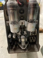
Here is what I'm working with.. If I plug the lathe into power the tubes are getting power and the transformers are humming and nothing will turn them off. Should there be a on switch just for this?
 

Attachments

  • 2022-12-19 12.47.28.jpg
    2022-12-19 12.47.28.jpg
    264 KB · Views: 14
  • 2022-12-19 12.47.42.jpg
    2022-12-19 12.47.42.jpg
    390.3 KB · Views: 27
  • 2022-12-19 12.47.44.jpg
    2022-12-19 12.47.44.jpg
    298.7 KB · Views: 12
  • 2022-12-19 12.48.03.jpg
    2022-12-19 12.48.03.jpg
    326.7 KB · Views: 12

rke[pler

Diamond
Joined
Feb 19, 2002
Location
Peralta, NM USA
It looks like someone's hotwired the power contactor - that's the device in the second picture. Normally the start button closes the PC which then holds through the hold points on the contactor until you release them with the stop button (the mushroom switch below the start button). This is all for your safety so that in a power loss the lathe defaults to off when the power returns. Honestly (and this is coming from someone not at all risk averse) I would get this repaired ASAP.

The switch next to the PC is for the coolant pump.

Normal operation would be to power the lathe up with the disconnect, wait 60- seconds for things to get warm (needed by tubes and here enforced by a 6NO60 timer tube) then press the "start" button to get field and armature (i.e. motor control). Someone's messed with this and you're going to have to try and track down what they've done.

Cal's written on this:


Cal Haines

Diamond
Joined
Sep 19, 2002
Location
Tucson, AZ
I agree with Russ, this is definitely not how the machine left the factory. The start button has been disconnected. I can't tell what's going on with the stop button, but it's possible that it's being used to control the contactor. Try pushing the stop button in and see if the contactor opens and shuts off the machine.

Russ can probably explain this further, but apparently on WiaD machines (unlike MG machines) main power is controlled by the fused disconnect switch on the back and the AC contactor only controls the drive circuit. Power is taken off prior to the main contactor to power the timer circuit, etc., which allows time for the tubes time to warm up. Once the 6NO60 timer closes, the start button can be pressed, allowing the main contactor to close and route power to the drive stage and motor. You should trace all the wires in the main contactor compartment and see where they go.

Note that anytime the main disconnect is closed, part of the tube drive circuit is powered. You need to turn off the main disconnect switch when you're done using the machine.

I can't tell from the wiring diagrams if WiaD machines used the same Cutler-Hammer (CH) contactor as motor/generator (MG) machines, but this is definitely not a CH contactor. Based on the heaters, it appears to be an Allen-Bradley contactor.

Here's a thread that discusses the start circuit using a different model Allen-Bradley contactor:

AFIK 10EEs shipped with momentary-contact start and stop buttons. The start button was normally open and pressing it would energize the coil circuit and allow the contactor to close. The stop buttons was normally closed and pressing it would break the coil circuit and shut off power. You appear to have a two-position stop button, which may have been wired to close the coil circuit when in the outer position and break the coil circuit when pressed in (this type of switch will stay depressed until the operator pulls it out). It's unknown if the 6NO60 timer is wired into the contactor's coil circuit or not.

The N15 heaters on your contactor are too small. They are probably left over from the machine being wired for 440 operation. You'll need to change those or the contactor will trip off long before you get to full load. If you have a fused disconnect on the back of the lathe, check the incoming fuses, they may be too small as well. (This would not be the first machine that was improperly rewired when converting from 440 to 220).

I'm not sure where you're at. In post #10, you indicate that the lathe will run. Is the problem not being able to turn it off?
 

Cal Haines

Diamond
Joined
Sep 19, 2002
Location
Tucson, AZ
That's certainly possible. The main contactor's coil is 220 VAC, so it has been at least partially converted. The heaters that are on there may be left over from where ever the contactor was previously used. (I seriously doubt it's original.) If it were once a 440 machine, I wouldn't rely on everything else having been done correctly to convert it to 220/240. Unfortunately, I don't know enough about WiaD machines to tell you what to check.

Were you able to get the spindle to run at some point?
 

zgoo

Hot Rolled
Joined
Dec 10, 2002
Location
Portland, Oregon
Funny I had a bad fuse out on a PUD transformer and was getting weird voltage. PUD came by and replaced the fuse any I now have 120,120,240 power again. The only way I could get the spindle to run was to push up manually on the contactor hold and the spindle would run, but that is it...
 

Cal Haines

Diamond
Joined
Sep 19, 2002
Location
Tucson, AZ
It sounds like the drive is working and the problem is with the main AC contactor; it's definitely not hooked up correctly. The first thing to do is to verify that the contactor's coil isn't burned out. Disconnect the wires from both terminals and measure the resistance between the terminals. It shouldn't read as shorted or open. I don't know off hand what you should read, but something in the range of 50 to a few hundred Ohms would be reasonable.

The next thing is to sort out is the wiring for the contactor's coil circuit. You need to trace and identify all the wires that are connected to the contactor's coil, heaters, and the terminal pair on the left side of the contactor, at the top. One wire should go to the spindle control switch in the headstock. There may be wires that go the a microswitch at the spindle lock on the left end of the spindle. Two wires should go to terminals B1 and B2 in the electronics unit (these are the wires to the timer tube). The remaining wires should go to the start/stop station on the front of the base, by the operator's knee. You ultimately need to reconnect the contactor and all the wires that terminate there per the wiring diagrams. Do you have wiring diagrams for the machine?


Top