hitandmiss
Titanium
- Joined
- Jul 31, 2010
- Location
- Rochester, NY USA
Hardinge HC troubleshooting info for variable speed change problems
Over the years several people have had problems with the HC variable speed unit that will not change speed properly.
The main problem starts with the electrical drawings are never with the machines and appear to be hard to find.
Coupled with a couple of not so obvious flaws that lead to very unexpected results see ****CAUTION**** below when trying to work on one of these with no prints.
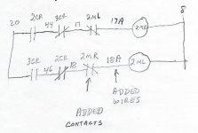
The schematic shown here is from CHB-8220. It is an early print from 1980.
The info shown should be close enough to trouble shoot speed control problems.

Component identification:
1DS Closed when spindle is running.
SS3 Selector switch to turn variable speed on or off.
2LS Limit switch to stop speed change motor when at end of travel.
2MR Contactor to run speed change motor to raise speed.
2ML Contactor to run speed change motor to lower speed.
2CR Plug in relay to control 2MR.
3CR Plug in relay to control 2ML.

Spindle must be running and SS3 turned on to change speed.
If speed is at maximum or minimum either 2 CR or 3CR will be pulled in, these relays are plug in and can be switched.
If the same problem persists, the next thing to check is the transistors located in the speed control station.
They are in sockets and can be switched. The top one operates 2CR for increasing speed. The lower one operates 3CR for lowering speed. If the attached relay is always on, the transistor is probably shorted E to C.
*** CAUTION**** Be advised, before manually operating either 2MR or 2ML, remove 2CR and 3CR. There is no manual or electrical interlocks for 2MR or 2ML and they can both be closed at the same time and cause real problems. If the speed is stuck at either limit, the appropriate contactor will have power as soon as you jog off the limit, and if you are holding the other one in, it gets ugly fast!
If the speed is midway and not able to be changed, see below picture:

The small transformer at the lower left should have 115-120 Volts between wires 8 and 20 (the lower terminals).
The complete print is here:

Bill
Wow, under "go advanced" when editing, you can edit the thread title, but it doesn't seem to update on the forum every time.
Over the years several people have had problems with the HC variable speed unit that will not change speed properly.
The main problem starts with the electrical drawings are never with the machines and appear to be hard to find.
Coupled with a couple of not so obvious flaws that lead to very unexpected results see ****CAUTION**** below when trying to work on one of these with no prints.
The schematic shown here is from CHB-8220. It is an early print from 1980.
The info shown should be close enough to trouble shoot speed control problems.

Component identification:
1DS Closed when spindle is running.
SS3 Selector switch to turn variable speed on or off.
2LS Limit switch to stop speed change motor when at end of travel.
2MR Contactor to run speed change motor to raise speed.
2ML Contactor to run speed change motor to lower speed.
2CR Plug in relay to control 2MR.
3CR Plug in relay to control 2ML.

Spindle must be running and SS3 turned on to change speed.
If speed is at maximum or minimum either 2 CR or 3CR will be pulled in, these relays are plug in and can be switched.
If the same problem persists, the next thing to check is the transistors located in the speed control station.
They are in sockets and can be switched. The top one operates 2CR for increasing speed. The lower one operates 3CR for lowering speed. If the attached relay is always on, the transistor is probably shorted E to C.
*** CAUTION**** Be advised, before manually operating either 2MR or 2ML, remove 2CR and 3CR. There is no manual or electrical interlocks for 2MR or 2ML and they can both be closed at the same time and cause real problems. If the speed is stuck at either limit, the appropriate contactor will have power as soon as you jog off the limit, and if you are holding the other one in, it gets ugly fast!
If the speed is midway and not able to be changed, see below picture:

The small transformer at the lower left should have 115-120 Volts between wires 8 and 20 (the lower terminals).
The complete print is here:

Bill
Wow, under "go advanced" when editing, you can edit the thread title, but it doesn't seem to update on the forum every time.
Last edited:


