guythatbrews
Hot Rolled
- Joined
- Dec 14, 2017
- Location
- MO, USA
I received this machine New Year's Eve. There is quite a bit of stuff out there regarding the HBX 360 but hardly anything on this lathe, so I'll try to add to the little that exists. Thanks in advance to all those that have posted about the somewhat similar HBX 360.
As always the thing arrived with no documentation. Machine shops are horrible about managing that stuff. About a week after emailing Cazeneuve I received a gracious reply. They can't locate the file on this machine but will be happy to help provide manuals and parts. I do not know what the time lag will be but yet but at least they made contact. I am anxious to get the manuals which best I can tell are non-existent on the web, at least complete English language manuals.
The machine is in very good condition. It has seen some use but not a lot. The bed ways and the cross slide ways are pristine. I doubt I will paint anything, at least anything major. Here's a shot after some disassembly.

First impression is this is a stout machine. And unique in some regards, like the HBX 360. Equipped with what Caz calls the drilling tailstock, referred to elsewhere as a capstan tailstock. It has a tracer and the best template holder I have ever seen. The template holder has a rack for flat templates and a set of centers for centered shafts. The centers are on a swiveling base which will make cutting tapers a breeze.
Unloading
The catalog weight is just short of 5000# and my 5000# lift with fork extensions had no trouble at all removing the lathe from the middle of a gooseneck trailer. The bubbas that delivered it had to be shown they bent the housing that holds some of the shifting mechanism when they picked it up. The housing protrudes below the bottom of the bed 1/2". They were unconcerned and reluctant to let me place 2/4's on the forks to prevent further damage, but I won the day. It is minor damage and hopefully not too bad to straighten out. The cross feed handle retaining ring was apparently missing so the handle fell off in transit and must be replaced.
Disassembling
I'm starting a bit after this process is underway, and will only describe the stuff that is out of the ordinary.
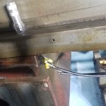
After a general wipe down the first thing removed was the right telescoping leadscrew cover. I got some insight from a you tube vid about HBX 360 tube removal. The HBX 590 is a slightly different process. It is worth noting that the leadscrew does not run in an oil bath like the HBX 360, but is greased. Maybe Caz realized the oil bath was overkill and prone to leakage, and a expensive PITA to replace seals. It will be pretty simple to retract the covers for periodical re-greasing, and does away with the common 360 leakage complaint. To start, remove the retaining nut in the leadscrew support block.

It really takes a special face spanner, but I shamefully used a screwdriver since it wasn't tight. But I'll make a tool for putting it back together. The tube can now be collapsed toward the carriage.
Next remove two sets of three bolts on the headstock retainer at the left end of the left cover. Unscrew the left telescoping cover from the carriage with a strap wrench. Unbolt the right leadscrew support block and tap it off the locating pins. The carriage should be somewhat to the left so as not to bend the leadscrew. Then the leadscrew, block, left tube, and left retainers can be pulled to the right bit. You'll probably have to tap on the retainers. The left end of the leadscrew, now visible, is captured in the retainers with a bearing locknut. You'll have to make a socket type wrench for this.

Make the prongs .150 wide x 1/4 long. The inside distance between the prong flats is .954. The od is 1.13 and the id is stepped out to clear everything in then way. The nut wasn't brutally tight. Use a padded vise grip to hold the leadscrew. Remove the left end woodruff key and the left retainers/bearing.
Move the carriage closer to the headstock. Pull the leadscrew assembly through the carriage to the right. The left tube is now free. Remove the square control rod. The right tube will be removed with the apron.
The cross slide is straight forward. Remove three bolts holding the handwheel support and unscrew the leadscrew out of the nut. Loosen the gib and withdraw the cross slide from the far side of the machine. I removed the compound rest before this step to lighten the load. Water soluble coolant had been used at some point but not much, or maybe this machine handles it well. The only real messy spot was the circular track for the compound nuts and it was filled with rusty gunk.

Luckily the gunk hadn't passed through to the top of the cross slide so no important stuff damaged. That coolant can trash a lot of stuff.
The cross slide is a massive 26.5" long and the dovetail ways only 23" so the ways are mostly covered. The compound rest can be moved along the compound anywhere and clamped there on the dovetails cut into the top of the cross slide, via the two square head screws shown above. The taper attachment is clamped similarly and so can be repositioned. This is a great design.
Now remove 4 bolts holding the apron. The apron will fall away easily once it is free of the shallow taper pins. Of course you don't have to remove the cross slide to remove the apron. Some chips and dirt on the back side of the apron. Amazing how swarf bounces around and lodges behind things. The tube may now be removed with an improvised strap wrench. I used vise grips and a length of sanding cloth. Not much clearance and a normal strap wrench is too thick to work.

The apron is open on the bottom and seems less busy than conventional lathes.

The gears are greased and the shafts run in needle bearings. They show very little wear. I may not do anything more than clean the gears and re-grease since it's pretty easy to get to this point at any time if needs must. I'm surprised the bottom is open. I think I will make a sheet metal cover. Always a chance of flicking gunk up in there when cleaning out the chip pan.
The longitudinal carriage clamp is a long pivoting shoe on the left apron end operated by and eccentric. Again, good design.

The gib that holds down the front of the carriage is on the right apron end and is a wedge split horizontally, with the expected gib adjusting screws.

I've got the saddle disassembled and cleaned and will show pics of that during assembly. It was full of the typical mayonnaise gunk. I'll source the three o rings in the lube system locally so I can get this back together and out of the way. Pretty sure they are 13mm x 9mm x 2mm buna-n. Gut feeling is it will be a slow process getting parts from Caz.
More to come.
As always the thing arrived with no documentation. Machine shops are horrible about managing that stuff. About a week after emailing Cazeneuve I received a gracious reply. They can't locate the file on this machine but will be happy to help provide manuals and parts. I do not know what the time lag will be but yet but at least they made contact. I am anxious to get the manuals which best I can tell are non-existent on the web, at least complete English language manuals.
The machine is in very good condition. It has seen some use but not a lot. The bed ways and the cross slide ways are pristine. I doubt I will paint anything, at least anything major. Here's a shot after some disassembly.
First impression is this is a stout machine. And unique in some regards, like the HBX 360. Equipped with what Caz calls the drilling tailstock, referred to elsewhere as a capstan tailstock. It has a tracer and the best template holder I have ever seen. The template holder has a rack for flat templates and a set of centers for centered shafts. The centers are on a swiveling base which will make cutting tapers a breeze.
Unloading
The catalog weight is just short of 5000# and my 5000# lift with fork extensions had no trouble at all removing the lathe from the middle of a gooseneck trailer. The bubbas that delivered it had to be shown they bent the housing that holds some of the shifting mechanism when they picked it up. The housing protrudes below the bottom of the bed 1/2". They were unconcerned and reluctant to let me place 2/4's on the forks to prevent further damage, but I won the day. It is minor damage and hopefully not too bad to straighten out. The cross feed handle retaining ring was apparently missing so the handle fell off in transit and must be replaced.
Disassembling
I'm starting a bit after this process is underway, and will only describe the stuff that is out of the ordinary.
After a general wipe down the first thing removed was the right telescoping leadscrew cover. I got some insight from a you tube vid about HBX 360 tube removal. The HBX 590 is a slightly different process. It is worth noting that the leadscrew does not run in an oil bath like the HBX 360, but is greased. Maybe Caz realized the oil bath was overkill and prone to leakage, and a expensive PITA to replace seals. It will be pretty simple to retract the covers for periodical re-greasing, and does away with the common 360 leakage complaint. To start, remove the retaining nut in the leadscrew support block.
It really takes a special face spanner, but I shamefully used a screwdriver since it wasn't tight. But I'll make a tool for putting it back together. The tube can now be collapsed toward the carriage.
Next remove two sets of three bolts on the headstock retainer at the left end of the left cover. Unscrew the left telescoping cover from the carriage with a strap wrench. Unbolt the right leadscrew support block and tap it off the locating pins. The carriage should be somewhat to the left so as not to bend the leadscrew. Then the leadscrew, block, left tube, and left retainers can be pulled to the right bit. You'll probably have to tap on the retainers. The left end of the leadscrew, now visible, is captured in the retainers with a bearing locknut. You'll have to make a socket type wrench for this.
Make the prongs .150 wide x 1/4 long. The inside distance between the prong flats is .954. The od is 1.13 and the id is stepped out to clear everything in then way. The nut wasn't brutally tight. Use a padded vise grip to hold the leadscrew. Remove the left end woodruff key and the left retainers/bearing.
Move the carriage closer to the headstock. Pull the leadscrew assembly through the carriage to the right. The left tube is now free. Remove the square control rod. The right tube will be removed with the apron.
The cross slide is straight forward. Remove three bolts holding the handwheel support and unscrew the leadscrew out of the nut. Loosen the gib and withdraw the cross slide from the far side of the machine. I removed the compound rest before this step to lighten the load. Water soluble coolant had been used at some point but not much, or maybe this machine handles it well. The only real messy spot was the circular track for the compound nuts and it was filled with rusty gunk.
Luckily the gunk hadn't passed through to the top of the cross slide so no important stuff damaged. That coolant can trash a lot of stuff.
The cross slide is a massive 26.5" long and the dovetail ways only 23" so the ways are mostly covered. The compound rest can be moved along the compound anywhere and clamped there on the dovetails cut into the top of the cross slide, via the two square head screws shown above. The taper attachment is clamped similarly and so can be repositioned. This is a great design.
Now remove 4 bolts holding the apron. The apron will fall away easily once it is free of the shallow taper pins. Of course you don't have to remove the cross slide to remove the apron. Some chips and dirt on the back side of the apron. Amazing how swarf bounces around and lodges behind things. The tube may now be removed with an improvised strap wrench. I used vise grips and a length of sanding cloth. Not much clearance and a normal strap wrench is too thick to work.
The apron is open on the bottom and seems less busy than conventional lathes.
The gears are greased and the shafts run in needle bearings. They show very little wear. I may not do anything more than clean the gears and re-grease since it's pretty easy to get to this point at any time if needs must. I'm surprised the bottom is open. I think I will make a sheet metal cover. Always a chance of flicking gunk up in there when cleaning out the chip pan.
The longitudinal carriage clamp is a long pivoting shoe on the left apron end operated by and eccentric. Again, good design.
The gib that holds down the front of the carriage is on the right apron end and is a wedge split horizontally, with the expected gib adjusting screws.
I've got the saddle disassembled and cleaned and will show pics of that during assembly. It was full of the typical mayonnaise gunk. I'll source the three o rings in the lube system locally so I can get this back together and out of the way. Pretty sure they are 13mm x 9mm x 2mm buna-n. Gut feeling is it will be a slow process getting parts from Caz.
More to come.