What's new
What's new

Dialog 4 upgrade

rimcanyon

Diamond
Joined
Sep 28, 2002
Location
Salinas, CA USA
OK, I realize that for most of you, a dialog 4 upgrade is ancient history. However, I bought Rich Klopp's D4 FP2NC, and my first project is to transfer the D4 to my machine. So the obvious question: what parts need to be moved? All boards in the console, the console keypads and the hand control? Or swap complete consoles and hand controls? Did Deckel publish upgrade instructions, does anyone have a copy they would share?
 

AlfaGTA

Diamond
Joined
Dec 13, 2002
Location
Benicia California USA
So here is my take having had both versions at one time or another.....
Easiest is just swap the entire operators console. Held on by 6 Allen bolts in the flange below the console it is not difficult to remove.....
Remove all he cables from the card cage and thread them into the base and then out the center hole.
Leave all the cards in place.
The consoles will interchange. There are parts in the D4 console that the D2 will not have...There is a card on the base with its ribbon cable that feeds the RS232 output port....

Also trade the entire large green cabinet...Just swap them. Likely the D4 machine will have the later servo cards (the piggy back versions which are more desirable and more repairable) The newer cabinet will likely not have the outlet for powering the high speed head, but you will have 6300 RPM spindle so its no longer needed.
Cards and software versions in the newer "PC" will be compatable with the newer control, easy!

Then you would want to do the normal maintenance on the new combination...clean all the servo tachometers, and set the drift and tacho .....
Might want to refresh the batteries while you are at it.

If you are getting a 2039 table with the encoder don't forget that you will need a Heidenhain converter box (EXE 610) that needs to be in between the table output cable and the required 4th axis card (NZP) .

That is one scary trailer......

Cheers Ross
 

rimcanyon

Diamond
Joined
Sep 28, 2002
Location
Salinas, CA USA
Thanks Ross. I will do that. The one step I have not done in the past is set the drift and tacho. I think you have posted the instructions before so I will look for them. The 2038 comes with an EXE 610.

The trailer is the same one I brought the FP2NC home on from your place, 10 years ago? Hard to remember. It is built to haul a Bobcat around so it is quite happy with a Deckel.
 

rimcanyon

Diamond
Joined
Sep 28, 2002
Location
Salinas, CA USA
The 1986 FP2NC has two cables at the bottom of the console, while the 1984 has only one. Both cables have round multi-pin connectors designed to fit a Heidenhain transducer box. But why are there two? I can understand one, for a 4th axis like the toolmaker's table.
 

Dan from Oakland

Titanium
Joined
Sep 15, 2005
Location
Oakland, CA
Those little itty bitty orange Home Depot ratchet straps scare me more than the trailer.............I know they are not holding much but........ Nice looking machine though!! Have fun!
 

AlfaGTA

Diamond
Joined
Dec 13, 2002
Location
Benicia California USA
AFAIK there are two round multi pin connectors connected with the control....
One is over at the "X" axis connection box (servo). That is for the tool change pendant...should be the same as your D2 machine.
On the under side of the operators console is a second round connector, that is for the manual pulse generator (electronic hand wheel )
Other connections on the console under side are the RCA jack for audio recording of programs (never used this) and the RS232 parallel port. There is also the knob that adjusts the display brightness....That's it on the factory setup.
Cheers Ross
 

AlfaGTA

Diamond
Joined
Dec 13, 2002
Location
Benicia California USA
Missed that, thanks Rich.

Dave:
If you look at the accessory connection plate (just below the "X" axis feed motor) you will see that on your Dialog 2 machine there are two rectangular connection sockets covered by tin caps....
On the later machine there are three such rectangular connectors.
The two smaller ones (full right and full left ) are connected to the two cables in the base of your control (D4)
The cable you want is the one that connects to the right hand socket (closest to the chip pan)
That connector is for the table readout and should be connected to your EXE 610 box that is needed for displaying the table rotary position.
The far left connector is listed as used for the measuring system......Its an aux connection of the X scale output...You won't need this, so the second cable is more or less superfluous. So its not an issue when you change over the control console to the older machine, you will only have the one cable to the EXE since you won't have that third socket at the "X" servo.

as a side note the larger rectangular socket is the connection for a powered 4th axis....(rotary table or NC dividing head) Plus there are dry break connections for hydraulic, compressed air and tachometer (small round socket)
Cheers Ross
 

rimcanyon

Diamond
Joined
Sep 28, 2002
Location
Salinas, CA USA
Ross, thanks for the explanation. I can see the extra connector below the X Axis motor. Did Deckel sell any attachments designed for the additional connector on the 86 machine? It seems strange for a company to add a feature without any reason.
 

rimcanyon

Diamond
Joined
Sep 28, 2002
Location
Salinas, CA USA
I found several posts on adjusting servo drift and tach. I think the top pot (labeled OFF) is for adjusting drift and the bottom pot (T) is for tach:
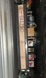
IMG_1169.jpeg

What is the middle pot for, labeled SW1?

The adjustment steps are as follows, compiled from the different posts.

Drift:
Set NRP dip switches 2&6 on
Turn main power ON
Turn control ON
(DD says to set METRIC in mode 16)
Set mode to 5 or 6, feed control to 100% and feed rate to 1000mm/Min.
Adjust OFF pots on X,Y and Z cards until control shows 0 on all axes
Turn control OFF and ON to check
Turn control and main power OFF
Set NRP dip switches all to off

Tacho:
Set NRP dip switches 2 & 5 on
Set mode to 6, feed control to 100% and feed rate to 1000mm/Min.
Turn main power ON
Turn control ON
Start an axis moving in + direction, note value displayed.
Adjust using Tach pot until axis display reads between 0.000 and 0.010, and to try to get as close to 0.00 as possible.
Repeat in - direction, and adjust until both directions read the same
Repeat for other two axes (or three if you have a 4 axis machine)
Turn control and main OFF
Set NRP dip switches all to off
 

rimcanyon

Diamond
Joined
Sep 28, 2002
Location
Salinas, CA USA
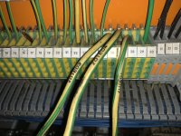
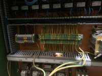
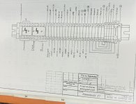
What is the correct way to wire the ground wires that come from the machine into the big electrical cabinet? D2 and D4 are quite different, hence the question.

Here is how I have it wired, best guess. E01 to 28, E04 to 27 and E03 to 26.

IMG_1175.jpeg

Here is how the D2 grounds were wired:

IMG_1164.jpeg

E01 comes from the Dialog Console, E03 is from the left side of the FP2NC chassis. Not sure where E04 is from.

The orange book would probably tell me if I spoke German:

IMG_1178.jpeg
 
Last edited:

rimcanyon

Diamond
Joined
Sep 28, 2002
Location
Salinas, CA USA
I think so but look at the wiring diagram above. It identifies the locations of Dialog, Stander and Support, whatever the latter two are. And it has some strange devices connected to ground in positions 31 through 35.
 

AlfaGTA

Diamond
Joined
Dec 13, 2002
Location
Benicia California USA
So they are German...can't help themselves.....PE is all the same (GROUND) don't think exact location makes any difference.
You need one ground cable at the end (10?) of the power connection block.
The other two cables can go anywhere on the PE block....The right and left end connectors are larger to accept the heavier cable.
Here is a shot of my D4 3150 machine...may be different from your later machine....but again don't think it matters....

full


Cheers Ross
 

rimcanyon

Diamond
Joined
Sep 28, 2002
Location
Salinas, CA USA
I have the D4 installed on my 1984 FP2NC, and the Drift and Tacho are set, although I noticed that both of them drift a bit as the control warms. The new green electrical cabinet is much quieter than the original, perhaps due to updated electricals. I have been reading manuals, learning D4. There are still a number of keys on the keyboard I haven’t identified (keys not on the D2 keyboard). So I am sure this is the first of several posts with questions about D4 commands not in D2.

First, re: tool compensation in D4, e.g. the command G17 T1.

E.g. if L =10 and A =2, and then these blocks are executed:
N005 G17 T1
N006 Z0

Then line N6 Z0 will move the tool tip to 2mm above the workpiece (assuming that Z0 was set by touching the reference tool prior to running the program). I.e. the program zero will be 2mm above the workpiece.

That seems kind of strange. I.e. every dimension in the program will need to be corrected if I use the allowance setting. Or do I have it wrong?
 

rklopp

Diamond
Joined
Feb 27, 2001
Location
Redwood City, CA USA
I have the D4 installed on my 1984 FP2NC, and the Drift and Tacho are set, although I noticed that both of them drift a bit as the control warms. The new green electrical cabinet is much quieter than the original, perhaps due to updated electricals. I have been reading manuals, learning D4. There are still a number of keys on the keyboard I haven’t identified (keys not on the D2 keyboard). So I am sure this is the first of several posts with questions about D4 commands not in D2.

First, re: tool compensation in D4, e.g. the command G17 T1.

E.g. if L =10 and A =2, and then these blocks are executed:
N005 G17 T1
N006 Z0

Then line N6 Z0 will move the tool tip to 2mm above the workpiece (assuming that Z0 was set by touching the reference tool prior to running the program). I.e. the program zero will be 2mm above the workpiece.

That seems kind of strange. I.e. every dimension in the program will need to be corrected if I use the allowance setting. Or do I have it wrong?
That A offset only applies to T1, assuming that L=10 was gotten by touching T1 off to a Z=0 surface. "A" is an allowance to leave all Z dimensions 2 mm oversize for T1, in case you want to measure and see how far you actually have left to take off to hit the Z dimensions on your part or to leave material for a finish pass with, say, a T1*1 with A=0. You can use negative A values if your cutter is acting undersize. Typically, A offsets are more valuable applied to cutter radius than length, but not always.
 

AlfaGTA

Diamond
Joined
Dec 13, 2002
Location
Benicia California USA
Difference is that all offsets on the D2 are local to the line where called...
On D4 its more conventional where every tool has an offset for both length and diameter and they are global within the program.....

I personally never use the "A" values. just program with those values at "0"
Then you can use the offset values to "tune" the exact size of the part you need.

you are going to have lots more fun with the D4.....Its a huge leap from the D2.

Cheers Ross
 

rimcanyon

Diamond
Joined
Sep 28, 2002
Location
Salinas, CA USA
A lot of the commands have allowance built in, e.g. G71,72,73,74 have parameters that define X,Y and Z finishing allowances. Then some of them also have a safety allowance in Z. In all the pocketing examples they call T1. So I am going to assume that A=0, as you both mention. Nice idea to use A and RA as finishing allowances (or compensation for an undersize cutter) in other code however.


Top