Isak Andersson
Aluminum
- Joined
- Nov 3, 2021
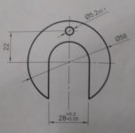
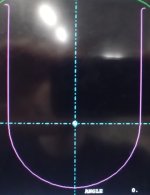
Hi. I'm trying to mill out a fairly simple shape but programming this in Mazatrol is anything but simple. The manual was no help either, it only confused me even further.
The machine I'm using has no Y-axis so I must use the C and X-axis to create a virtual Y-axis.
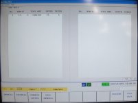
1. I get this error 434 - "No assigned tool in tool file". Does this mean I can't just define the tool in tool data? I've honestly never used the tool file before because I can't figure out how it's supposed to work.
2. If I do use the tool file, where do the offsets go?
3. How does it know which tool slot to go in?
4. How does it know what direction the tool is mounted in? From the program or what?
5. Where is the radius compensation? All I see is length compensation and the tool file has no compensation whatsoever.
6. In the LINE LFT unit (I assume this is the right unit for this) what exactly do all the parameters mean and which ones are necessary to input?
7. How do I adjust the Z coordinate for the chamfer tool? Surly I must tell it somehow where the top and bottom chamfers start, right?


