What's new
What's new

2001 Integrex spindle orientation clamp out of position

JSL_MFG

Aluminum
Joined
Apr 24, 2022
Hey guys,

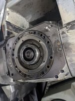
I have a 2001 Mazak Integrex 100-IISY, which has a 10k KMX spindle. My spindle orientation was off, and I adjusted it using variable SP07. However, I discovered that when the milling spindle clamps, even after being orientated, the spindle moves out of orientation by about 0.5 deg. You can actually see the holder turn slightly when the clamp is activated.

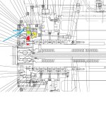
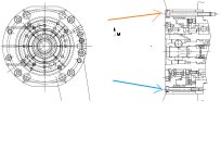
Called Mazak, and they said to pull the front cover off and attempt to adjust the high-index coupling. The process sheet they sent doesn't appear to be for the KM spindle though, and I don't want to tear into this machine any further until I've got a better understanding of what I'm doing. Does anybody have some advice?
 

Attachments

  • Int Mk2 Mill Spindle Adjustment.pdf
    472.9 KB · Views: 12

JSL_MFG

Aluminum
Joined
Apr 24, 2022
just follow the procedure. SP07 is electrical orientation. Coupling is a mechanical lock. You just have to adjust it mechanically.

I pulled the cover off, and there were no pins to remove. There's another cover that appears to be covering the spindle bearings, but I don't want to take that guy off if I don't have to. The procedure is definitely for a newer model machine.
 

noname777

Cast Iron
Joined
Aug 24, 2018
Location
NSW , Australia
IT looks like this procedure is for CAPTO socket. Does it?
and it looks like it is for MK1 INT generation.

HAve you got parts manual for your particular machine?
 

noname777

Cast Iron
Joined
Aug 24, 2018
Location
NSW , Australia
see this. YELLOW part is moving part. RED is attached to rotary part. GREEN is what is attached to spindle case. You need to undo bolts I pointed with the arrow and try to move this part of the coupling, make it square. If that is the design you have when it comes to upper milling head. 12000RPM KM63.
 

Attachments

  • Untitled2.jpg
    Untitled2.jpg
    309.8 KB · Views: 7

JSL_MFG

Aluminum
Joined
Apr 24, 2022
Great question, how about now?
 

Attachments

  • without_ring.jpg
    without_ring.jpg
    548.1 KB · Views: 6
  • with_ring.jpg
    with_ring.jpg
    554.9 KB · Views: 6

noname777

Cast Iron
Joined
Aug 24, 2018
Location
NSW , Australia
some of them will have tapered pins, deep inside. You have to find small diameter bar and screw it in , and after use it as a slide hummer. Yes?????
 

Attachments

  • without_ring.jpg
    without_ring.jpg
    896.4 KB · Views: 6

JSL_MFG

Aluminum
Joined
Apr 24, 2022
That makes a lot of sense, but every hole on that face is blind, except for the coolant holes. If there is a pin in the holes, it's not tapped from the back side for removal.
 

noname777

Cast Iron
Joined
Aug 24, 2018
Location
NSW , Australia
May be they didn't install them? and everything can be moved back and than just assembled back. You never know. Design modification. Cost savings. Who knows. If you dont have them for sure, than make it square and tighten bolts.
 

JSL_MFG

Aluminum
Joined
Apr 24, 2022
You might be right. I will remove that center cover and see what's going on beneath it. Regardless, the procedure says to loosen the "six bolts shown in the photo at right," and there aren't any bolts there to loosen, so hopefully, I can get a better eye on things when that last cover comes off.
 

noname777

Cast Iron
Joined
Aug 24, 2018
Location
NSW , Australia
those two cuts from parts manual is all you need to know about how it is built.
See the difference in between these two bolts. One bolt is for front cap. Another is for mill drive itself to be attached to upper turret
 

Attachments

  • Untitled5.jpg
    Untitled5.jpg
    340.6 KB · Views: 4

JSL_MFG

Aluminum
Joined
Apr 24, 2022
they made few diff generations . you need to have correct parts manual to understand what it is made of
I was able to get to the index coupling thanks to your help. Oddly enough, there were no pins anywhere in the assembly. Even the index ring doesn't have pins, which is a bit concerning. My only question now is how to properly align this thing though. What should the index ring be square to? The process sheet says to loosen the bolts and adjust the position to get the teeth to mesh. In an ideal world, I'd orient my spindle to home, run an indicator across the teeth and get it in line. I can't do this while the machine is powered up, or hydraulic oil will start shooting out of the turret. Any tips?
 

Attachments

  • Index_coupling.jpg
    Index_coupling.jpg
    735.1 KB · Views: 5


Top