What's new
What's new

Mazak Quick Slant 30N CAM T4 rescue or retrofit?

B.V.

Plastic
Joined
Dec 20, 2022
Location
Belgium
Hi to all,

I recently bought a Mazak Twin turret Quick Slant 30N from a company.
A little history of this Mazak, the machine had run years without huge problems according to the company, daily making hydraulic pistons as its only job. As they bought a bigger Haas, the Mazak need to make some room for the Haas, so I bought this nice lathe for my workshop. Unfortunately, i never saw the machine working, it was just being moved when i went looking it. But I trusted the company that the machine works without problems.

So, I was very happy about this purchase. I brought it home, get it in, give it a clean, all good until I powered up few days ago...
I switched on the main switch, cooling fans are running, so all seems good.
Next step, switch on the NC control. Red led next to the ON button comes on, some relays are kicking in, hydraulic pump delivers pressure, spindle motor fan comes up. So far, so good.

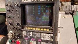
But then nothing happens anymore except for the NC alarm led that comes on. No CRT display, no ready led, no movement of the turret, tailstock, spindle, ...
Looks like the NC control is almost completely dead.

Next day, I resumed to try getting this Mazak alive. But it gets worse. When pushing the ON button, relays kick in but as soon as I stop pushing the ON button, machine goes back to off state. Tried a couple of times, no succes...
15min later, tried again. Machine goes in ON state together with the led in the ON button but that is all, no hydraulic pressure an no cooling fans.

Continuing today, I powered up the Mazak, Relays kick in, hydraulic pump along with fans come on but still no display. Only change is the NC alarm led isn't on.
My first thought was the backup batteries are dead. Machine hasn't been powered for about 14 days until now.
I measured the voltage off the 3 backup batteries: FX784-8: 3.71V, FX784-9: 3.92V, FX727: 3.84V
Anyway, I ordered 3 new 1500mAh NiMH phone batteries to be sure they are new and good. Hopefully I get them this week.

I checked the leds on the boards:
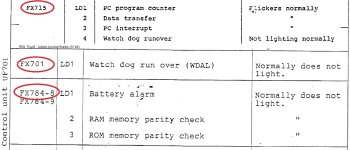
FX 701: WDAL is off but after a certain time it comes on.
FX784-8: PE1 is on, PE2 is off
FX 715: AL off, IT blinks, BA is on but very weak, RDY is on.

Measured the voltage to de CRT which is 106V, should be ok. Fan behind the CRT is running.

Can someone give me advise about this?
Now I am blaming myself that I bought this Mazak without seeing it working...

My last option is to retrofit this machine with a CS-Lab CSMIO control based on Mach3 but i would definitely like to try the mazatrol control, only if the repair cost is within limits.
Last two days, I got a lot of information from this forum about Mazak controls so hopefully, I get this Mazak saved from the scrapyard with a little help.

Thanks in advance!
KR, Bart
 
Last edited:

B.V.

Plastic
Joined
Dec 20, 2022
Location
Belgium
A little update,
Today, exactly 24h after measuring the voltages of the batteries just after powering off the Mazak, I measured the voltages again:
FX784-8: 2.9V
FX784-9: 3.9V
FX727: 3.78V

Looks like the FX784-8 board battery starts to loose its voltage very quick compared to the others.
Almost 1V voltage drop in 24h and the machine was unpowered for 14days...
Don't know how low the voltage may drop to let the FX784-8 loose its memory but i'm 99% sure that the memory on the board is gone.
So the battery definitely needs to be replaced. The new ones are coming in tomorrow.

Next question, how can i recover/re-initialize the T4 control? Has anyone a manual or bulletin to do this without the monitor?
Thanks!!
 

noname777

Cast Iron
Joined
Aug 24, 2018
Location
NSW , Australia
u dont really measure voltage drop when it comes to back up battery, more like the DC current your PCB board takes when battery is connected and machine is OFF. Of cause you do it once you know how to re initialize T4 control
 

B.V.

Plastic
Joined
Dec 20, 2022
Location
Belgium
Yes, but I don't have an accurate µA multimeter so the voltage of the battery is my only indicator right now.
And as the current battery is a Ni-Cd type, it could have a high internal discharge rate that is not measurable.
I will check the charge and discharge voltage/current after initializing and retrofit the new Nimh batteries.
 
Joined
Nov 19, 2007
Location
marysville ohio
Hi to all,

I recently bought a Mazak Twin turret Quick Slant 30N from a company.
A little history of this Mazak, the machine had run years without huge problems according to the company, daily making hydraulic pistons as its only job. As they bought a bigger Haas, the Mazak need to make some room for the Haas, so I bought this nice lathe for my workshop. Unfortunately, i never saw the machine working, it was just being moved when i went looking it. But I trusted the company that the machine works without problems.

So, I was very happy about this purchase. I brought it home, get it in, give it a clean, all good until I powered up few days ago...
I switched on the main switch, cooling fans are running, so all seems good.
Next step, switch on the NC control. Red led next to the ON button comes on, some relays are kicking in, hydraulic pump delivers pressure, spindle motor fan comes up. So far, so good.

But then nothing happens anymore except for the NC alarm led that comes on. No CRT display, no ready led, no movement of the turret, tailstock, spindle, ...
Looks like the NC control is almost completely dead.

Next day, I resumed to try getting this Mazak alive. But it gets worse. When pushing the ON button, relays kick in but as soon as I stop pushing the ON button, machine goes back to off state. Tried a couple of times, no succes...
15min later, tried again. Machine goes in ON state together with the led in the ON button but that is all, no hydraulic pressure an no cooling fans.

Continuing today, I powered up the Mazak, Relays kick in, hydraulic pump along with fans come on but still no display. Only change is the NC alarm led isn't on.
My first thought was the backup batteries are dead. Machine hasn't been powered for about 14 days until now.
I measured the voltage off the 3 backup batteries: FX784-8: 3.71V, FX784-9: 3.92V, FX727: 3.84V
Anyway, I ordered 3 new 1500mAh NiMH phone batteries to be sure they are new and good. Hopefully I get them this week.

I checked the leds on the boards:
FX 701: WDAL is off but after a certain time it comes on.
FX784-8: PE1 is on, PE2 is off
FX 715: AL off, IT blinks, BA is on but very weak, RDY is on.

Measured the voltage to de CRT which is 106V, should be ok. Fan behind the CRT is running.

Can someone give me advise about this?
Now I am blaming myself that I bought this Mazak without seeing it working...

My last option is to retrofit this machine with a CS-Lab CSMIO control based on Mach3 but i would definitely like to try the mazatrol control, only if the repair cost is within limits.
Last two days, I got a lot of information from this forum about Mazak controls so hopefully, I get this Mazak saved from the scrapyard with a little help.

Thanks in advance!
KR, Bart
mach 3 on a Mazak?!!!!!!! All the home shop Harry's will like that! Bonus! You will reduce its capabilities by about 90 percent. What a deal.
 

B.V.

Plastic
Joined
Dec 20, 2022
Location
Belgium
mach 3 on a Mazak?!!!!!!! All the home shop Harry's will like that! Bonus! You will reduce its capabilities by about 90 percent. What a deal.
Yes indeed, but that's my very last option.
I'm just getting started to reanimate the Mazatrol, were not giving up yet ;-)

Took some measurements (48h after power off) of the batteries on the boards:
FX784-8: 2.65V
FX784-9: 3.91V
FX727: 3.81V
Looks like one battery is getting tired...

But I just got the new phone battery packs in and get these installed tomorrow. Is there a special procedure to change these?
I read a lot of different stories about changing them:
- Load the supercap first by powering on a few minutes, then power off and quickly change the batteries before the supercaps loose their charge
- Just change batteries
- Changing batteries and unloading supercaps
Am I right that it doesn't really matter for my situation, as my control memory already messed up?

But I still need a re-initialization to do. Does anyone have a good manual to do this please?
 

noname777

Cast Iron
Joined
Aug 24, 2018
Location
NSW , Australia
Yes, but I don't have an accurate µA multimeter so the voltage of the battery is my only indicator right now.
And as the current battery is a Ni-Cd type, it could have a high internal discharge rate that is not measurable.
I will check the charge and discharge voltage/current after initializing and retrofit the new Nimh batteries.
u don't really measure what memory chips do consume, more like searching for abnormalities. That is all u do. If PCB board takes a lot, there is a leaky component, either chip itself or capacitor or whatever.
 

Overland

Hot Rolled
Joined
Nov 19, 2017
Location
Greenville, SC
Is there a maintenance tech at the place you bought the machine from that could help, after work or weekend or something ?
Also, when I got my machine, I called Mazak service; they did try to guide me. Then I found a local freelance tech that was great.
Good luck,
Bob
 

B.V.

Plastic
Joined
Dec 20, 2022
Location
Belgium
Is there a maintenance tech at the place you bought the machine from that could help, after work or weekend or something ?
Also, when I got my machine, I called Mazak service; they did try to guide me. Then I found a local freelance tech that was great.
Good luck,
Bob
Yes I spoke to him but he doesn't know much more about the problem.
He gave me the number of a service man, I'll contact him after Xmas season if I don't find the solution myself.

This morning started to change the batteries, here's what I did:
First of all, I measured the voltages of all boards:
FX784-8: 2.45V
FX784-9: 3.89V
FX727: 3.79V

Next, I turned on the power and control. All leds came up on the control panel and nothing started up, never seen that before. After 5 seconds, I turned off the control, waited 5 more seconds and turned the control back on. Again all leds came up and after 10 seconds waiting, the hydraulic pump started and I thought seeing a flash on the display together with a spark sound but nothing more...

I changed the batteries and drained the supercaps to 0.00V to re-initialize all 3 boards.
Put all boards back in the slots and gave it a shot. Control comes on with the pump starting after a few seconds but nothing more, the same as few days ago.

u don't really measure what memory chips do consume, more like searching for abnormalities. That is all u do. If PCB board takes a lot, there is a leaky component, either chip itself or capacitor or whatever.
I took the boards and batteries back out and measured the supercaps voltages. They are about the same voltage of the batteries in the beginning and slowly dropping in time, except for FW784-8, which was dropping 3 times faster than the others. It could mean that there's a leak or bad component on the board or the board effectively consuming a lot more due to more IC on it...

Can't do anything about that right now so I put everything (at 0.00V) back in an tried again. What I noticed was that the hydraulic pump started running as soon as I pushed the ON button on the control panel. All the other time it waited a few seconds to start?? The rest is all the same. Seems like the control is not totally fresh in the head...

So the search continues...
Thanks for all the answers by now and Merry Xmas to all!
 
Last edited:

noname777

Cast Iron
Joined
Aug 24, 2018
Location
NSW , Australia
FX 701: WDAL is off but after a certain time it comes on - this is your problem. See if all boards are clean and there is no coolant or some other deposits on PCB tracks. You can also with a help of tiny flat screwdriver move a bit memory chips in their sockets. Just a tiny move.

Hydraulic pump is activated with MOT relay? And MOT is activated after SB is activated? SB is activated with NC READY signal ON. If my logic is correct, NC boots , starts hydraulics and after goes into WDT alarm mode. May be ROM memory is corrupted, and it cant go past certain logical address.


Also this doesn't make sense:

I checked the leds on the boards:
FX 701: WDAL is off but after a certain time it comes on.
FX784-8: PE1 is on, PE2 is off
FX 715: AL off, IT blinks, BA is on but very weak, RDY is on.


, books tell something different. Why?
 

Attachments

  • s-l1600.jpg
    s-l1600.jpg
    450.3 KB · Views: 6
  • Untitled.jpg
    Untitled.jpg
    159 KB · Views: 6
Last edited:

B.V.

Plastic
Joined
Dec 20, 2022
Location
Belgium
FX 701: WDAL is off but after a certain time it comes on - this is your problem. See if all boards are clean and there is no coolant or some other deposits on PCB tracks. You can also with a help of tiny flat screwdriver move a bit memory chips in their sockets. Just a tiny move.
At the bottom, the boards are covered with a layer of coolant vapor dirt mixed with dust, blown by the cooling fans. Yesterday I removed with isopropanol alcohol the most of the goop from the boards that I took out to change the batteries. Maybe I should check the others as well.

I just read this thread from GP tech: https://www.practicalmachinist.com/...ll-need-help-getting-it-running.321171/page-4
His machine had a lot of the same symptoms as mine. Maybe, I have the same problem spooking around...

Hydraulic pump is activated with MOT relay? And MOT is activated after SB is activated? SB is activated with NC READY signal ON. If my logic is correct, NC boots , starts hydraulics and after goes into WDT alarm mode. May be ROM memory is corrupted, and it cant go past certain logical address.

As I read it from the schematics, MOT is the hydraulic pump relay and is directly controlled by the SB relay indeed.
 
Last edited:

B.V.

Plastic
Joined
Dec 20, 2022
Location
Belgium
I personally seen many times this coolant, sitting on PCB boards, corroding PCB tracks.
Today, I did some cleaning of the boards and suddenly, my eye dropped on a corner of a PCB track of the FX 727 board where some of the green protecting layer came loose.
Did a continuity check on the damaged tracks and for the wide track: 362 Ohms instead of the original 0 Ohms...
Carefully scrapped the green layer off and there it is:
20221227_162453.jpg
Followed the track and guess what, this track is the VCC+ supply for half of the RAM chips coming from the supercap...

I repaired the PCB by soldering a piece of copper wire over the damaged track:
20221227_163045.jpg

20221227_163100.jpg

The other little track was not damaged, only the protection layer came loose. I sprayed a new layer over it and put it back in.
Ready to put the control on and tadaa:
20221227_172330.jpg

I moved the turrets and that's all working at first sight.
That made my day, still have a parity alarm on FX784-8 (PE1 led on) but that is not for today.
Also is the brightness of the monitor very low. There's a potmeter on the back of the monitor next to the connectors, could that be a brightness control? It was sealed from factory but it seems to be turned in the past. Does someone know what this potmeter does?

Thanks for all the support by now!
KR, Bart
 
Last edited:

B.V.

Plastic
Joined
Dec 20, 2022
Location
Belgium
Today, I was struggling with the 22 parity alarm error.

I tried the memory re-initialization with dipswitch-3 to off. Don't know if this works but I assume it does.
Next parity reset with dipswitch-2 to off until parity led on FX784-8 goes off but this doesn't work. After 10 times power on - off cycling with 10 seconds in between, I gave up. The led still remains on.

Put the switch 2 back on and started the NC. Parity alarm is still on the display as the parity led (led2) on the FX784-8 board together with NC alarm + NC ready led on the control.
I started filling all parameters on the display. All parameters were weird and most were asterisks.
So after filling in all parameters, I erased all programs and tools + settings, as described in the service bulletin.
Parity alarm still on and now, error 20 - emergency stop came on.

Next, I repeated everything again.
I repeated re-initialization by flipping switch 3.
Did parity reset 5 times by switch 2.
Started NC with parity led still on + parity alarm active + NC alarm on control and NC ready OFF.
I looked into the parameters, they are all intact as I have programmed them??
Looks like the re-init and parity reset doesn't work?
 

B.V.

Plastic
Joined
Dec 20, 2022
Location
Belgium
Little update:
I removed the boards with batteries, drained the caps of all boards put them back in and started again.
Parity led on FX784-8 and F727 came on. All parameters are random so initialization worked.

I did the parity reset once and the led on FX727 immediately went off while FX784-8 still on.
Could not get the parity correct on the 784-8...
Is my FX784-8 fried to death?
 

noname777

Cast Iron
Joined
Aug 24, 2018
Location
NSW , Australia
All parameters were weird and most were asterisks-------- I think this is good indication that memory wasn't cleared properly. I would assume, the logic behind RAM memory initialization, is to make all RAM memory cells ZERO. Once you see everything as ZEROs, than memory was cleared. That is how I understand it.

And that is why MITSUBISHI released the document ( ages ago) where you have to force CPU board "to write" ZEROs into all available RAM memory, otherwise all these funny T2-T6 controls wont boot themselves or have unexplainable issues.
 

B.V.

Plastic
Joined
Dec 20, 2022
Location
Belgium
All parameters were weird and most were asterisks-------- I think this is good indication that memory wasn't cleared properly. I would assume, the logic behind RAM memory initialization, is to make all RAM memory cells ZERO. Once you see everything as ZEROs, than memory was cleared. That is how I understand it.

And that is why MITSUBISHI released the document ( ages ago) where you have to force CPU board "to write" ZEROs into all available RAM memory, otherwise all these funny T2-T6 controls wont boot themselves or have unexplainable issues.
This makes sense ^^^

I tried the other way, with dipswitch 8 to off position and RS232 link.
No pump, fan, control led or display (just lines) comes on and WDAL led on FX701 goes on. Think this is normal?
Also, there is no communication with PuTTy (hyperterminal alternative).

I don't have the pinout of the 25pol SUB-D connector on FX701, I assume that it is the classic pinout and straight connection?
Of should I use a NULL modem cable?
 

noname777

Cast Iron
Joined
Aug 24, 2018
Location
NSW , Australia
I done it myself twice on T2 control ages ago and I think I tried few RS232 cables. Check ATTACHED PDF, it shows SCN1 connector pinout.

I also have this (below) from someone else on the forum :


Found another reset procedure that involves using the SCN1 RS232 connector on the FX701 board.
I was able to connect to it using PuTTY.
you have to copy and paste the line in otherwise you get carriage returns when pressing comma.
Low and behold the NC has powered up and the display is working, but I still can't get to the parameters screen.
All I get is a flashing cursor at the top of the screen and Z axis drive error. For what ever reason the Z axis servo is now tripping out, but the Freqrol comes on ok in the READY state when the NC is powered up.
174467174468
link is to the procedure, I tried to attach the PDF but it was too big.

T2 reset FX72 using RS232.pdf - Google Drive (https://drive.google.com/file/d/0B8rvWQY91XAfblV5bzNLTkdPMjg/view?usp=sharing)

Also when dipswitch 8 is flipped the screen comes on with diagonal scrolling lines


P.S, it looks like it has to be null modem as procedure is talking about Xon/Xoff software hand shake:

X-ON / X-OFF​

The X-ON X-OFF operates by sending the control characters along the data line from the equipment receiving the data. The "X" in the name means "transmitter," so XON and XOFF are commands for switching a transmitter on or off, respectively.

When X-ON is received at the transmitting end data transmission is started.

Once the input buffer on the terminal or printer starts to become full the X-OFF character is sent to stop the data. When sufficient space appears in the buffer X-ON can be sent to the transmitter to resume the data flow.

The actual character or signal for XON is the same bit configuration as the ASCII Ctrl-Q keyboard combination. The XOFF character or signal is the Ctrl-S character.
 

Attachments

  • Mazak T2 T3 T4 How to Create an NC Backup Using CNCPCWIN.pdf
    164.1 KB · Views: 4
Last edited:

B.V.

Plastic
Joined
Dec 20, 2022
Location
Belgium
I dug deep in my storage room and found an other RS232 cable which did work with the Mazak!
Cleared out the board and all parameters were gone and filled with 0's finally.

BUT, the parity error still remains on FX784-8.
I tried all sort of sequences to reset parity, no luck...

So the only thing remaining is replacing the fx784-8 board (together with 784-9) I guess? Someone here who knows the weak spots of this board?
I studied electronics so I'm curious about it and might solve this myself with a bit of luck.

Or could there be something else going on?


For the other members that have questions about the RS232 procedure, this is what I noticed:
Moving switch 8 to off makes my Mazak doing this on startup:
- FX701 WDAL comes on
- Display throws horizontal lines
- No fans are coming up (except these in the cabinet)
- No hydraulics
- Just few relays clicking in the cabinet
- If the RS232 connection is correct and running, hyperterminal (or equivalent) is automatically showing: Meldas Monitor V3.3 ... Baudrate 9600
After typing in the command and pressing enter, the Mazak does NOT answer on hyperterminal but it DOES clear the memory. Don't get confused.
Simply turn off the control and all parameters are 0.
 
Last edited:


Top