What's new
What's new

Has anyone built an LVDT amplifier/signal conditioner?

rhb

Aluminum
Joined
Apr 27, 2019
Location
A small town in central Arkansas
I've bought a few LVDTs on ebay. Before I launch into designing a readout I thought I'd see if anyone else has done this.

Analog Devices makes a couple of parts, the AD598 and AD698, which are a complete analog implementation. All that's needed is a display of the output voltage properly scaled. However, they are fairly pricey which I find surprising.

So does anyone know anything about designing and building a readout for random LVDTs?
 

SeeFair

Plastic
Joined
Oct 20, 2015
I designed and built one for a national lab back in the 1980's, before those chips were available.

There's a lesson that some engineers learn: if you can buy it, then buy it; it's not worth wasting the time to design and build a monument to your own engineering prowess when an acceptable commercial alternative is already available. Those AD chips will make a much better amplifier than you could possibly cobble together out of more discrete parts. Spend the money!

If you want to learn about synchronous demodulation, this might not be the best place to start.
 

rhb

Aluminum
Joined
Apr 27, 2019
Location
A small town in central Arkansas
That's a nice looking build.

My preference is to buy a working or repairable B&S 599-1021 or similar if I can find one at an acceptable price. Building something is "Plan B".

At the moment I simply want to learn more about how the commercial units are constructed. The circuits described in "Position Sensors" by David Nyce are just simple center tap full wave bridges followed by a differential amplifier and low pass analog output filters. Ideally I'd like to find schematics for various implementations.

Unfortunately, Nyce has apparently never read "Mr. Hewlett, Max Wein and a Rainy Sunday Afternoon" by Jim Williams. Nyce notes that the Wein bridge is a popular primary signal source, but then states it has too much distortion. Williams made a prototype after a couple of iterations which had THD below the measurement floor of the best THD meter made at the time. That puts Nyce's expertise somewhat under a cloud.
 

SeeFair

Plastic
Joined
Oct 20, 2015
Thank you for the reference to that book from Jim Williams. I did not know it existed, and he was one of my early heroes. To this day, I only understand about half of what he wrote.

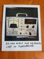
With regard to the signal source for your amplifier: again, I suggest you buy it instead of making it. The pictured amplifier achieved sub-microinch resolution using a (Burr-Brown) oscillator with 100x the distortion described in the Jim Williams blurb.

A quick look on the web produced this hit. I read a bit of it and it seems like a pretty fair treatment of synchronous detection.
 

CarbideBob

Diamond
Joined
Jan 14, 2007
Location
Flushing/Flint, Michigan
My only input is that this not an easy project if you want accuracy over a decent range.
$100 or so dollars for a chip. If your time is worth $1.00 per hour maybe better to buy.
If your free time is free or learning time????
Yes, I have done it rather than buy so I for sure get that side.
Bob
 
Last edited:

rhb

Aluminum
Joined
Apr 27, 2019
Location
A small town in central Arkansas
Thanks for the link. That was quite useful.

The AD datasheets have been very informative. I need to determine the characteristics of the LVDTs that I have.

The LVDT jargon is a bit weird to an RF person.

I need to find some shafting to fit the thread of the core. Once I have that I can measure using my Instek MSO2204EA using the arbitrary waveform generator and the DSO math functions while looking at the primary and 2 secondary signals as well as as the transfer functions implemented by the AD chips, the ratio A/B or (A-B)/(A+B) .

For serious measurements my Keysight 33622A AWG and HP 34401A DMM should provide excellent data via GPIB. That's a 40 ppm error reading the voltage difference at 50 Sa/s. That's with single PLC measurements.
 

SeeFair

Plastic
Joined
Oct 20, 2015
Bob has it quite right. Prototyping low-noise electronics takes a lot of time. You have to spend years with no girlfriends, smoking lots of cigarettes and drinking tab before it comes a bit quicker, but in my experience it never really comes quick (shoulda chosen the girlfriend and quit smoking). And then there's the fact that the electronics is only one part of it. LVDT bearings, stylus preload, temperature control, and calibration, among others, are all waiting to bite you.

If you're only interested in learning the theory, synchronous demodulation is a special case of a lock-in amplifier. Google that and add one to your expensive equipment list.
 

rhb

Aluminum
Joined
Apr 27, 2019
Location
A small town in central Arkansas
This is completely bizarre. I post a query asking for information. And to show I've done my homework mention that I'm looking at the AD598 and AD698.

The result is a bunch of posts telling me not to *consider* designing a circuit circuit instead of buying one of the chips I referenced. Even though I never said anything about designing a discrete circuit.

The AD offerings are quite sophisticated. I would not consider building anything that complex. As for "synchronous demodulation" that's quite a mouthful for summing the integral over a half period. And not unfamiliar if you play with radio. Except we traditionally call them "detectors" instead of "demodulators".

A computer sound card and some simple software will do everything needed to use a 3 winding DVT.
 

SeeFair

Plastic
Joined
Oct 20, 2015
From Raylan Givens: "If you run into an asshole in the morning, you ran into an asshole. If you run into assholes all day, you're the asshole."

There ought to be a corollary for PM.
 

CarbideBob

Diamond
Joined
Jan 14, 2007
Location
Flushing/Flint, Michigan
Never said "not to *consider* designing a circuit".
Just said it can be frustrating.
Unsure range, accuracy or update speed needed. 1/10 micron and less at 10 or less msec so way different that a thou at twice a second.
These toys are not linear, never the same for two probes and the circuits can be super temp and voltage sensitive. (garbage in, garbage out)

But hey, the only way to learn is to build and test it. I am all for that and say go for it.
You have the basics and some understanding. There must be fifty plus ways to build one. It is not hard to get readings out of these.
Bob
 
Last edited:

CarbideBob

Diamond
Joined
Jan 14, 2007
Location
Flushing/Flint, Michigan
Hmm, I now feel bad.:dunce:
Think the OP has a reasonable question.
We must have members still here who have done this and know the plus and minus sides.
The details that trip ya and keep you up at night with "Why don't you work right".
Bob
 
Last edited:

Bakafish

Cast Iron
Joined
Feb 21, 2022
Location
Tokyo Japan
Hmm, I now feel bad.:dunce:
Think the OP has a reasonable question.
We must have members still here who have done this and know the plus and minus sides.
The details that trip ya and keep you up at night with "Why don't you work right".
Bob
You didn't do anything wrong, just that the OP is some kind of performative troll. Everything he proposes, no matter how difficult or farfetched, he trivializes as easy, he name drops everything he can (the gratuitous itemization of his bench gear for example), he never provides the pictures, evidence or methodology that would confirm anything he is actually doing, and I have yet to see him complete any of his audacious (but 'barely an inconvenience') schemes. He wants attention and most of all for people to take him seriously and to think he's more capable than he's so far proven to be. Maybe have a gander through some of his other threads...
 

Straightedge

Hot Rolled
Joined
Mar 17, 2009
Location
Germany/California
I've bought a few LVDTs on ebay. Before I launch into designing a readout I thought I'd see if anyone else has done this.

Analog Devices makes a couple of parts, the AD598 and AD698, which are a complete analog implementation. All that's needed is a display of the output voltage properly scaled. However, they are fairly pricey which I find surprising.

So does anyone know anything about designing and building a readout for random LVDTs?
The AD598 and AD698 are pretty handy ICs but I've never used them in anything I had to give to a customer. Over the years, I've rolled my own LVDT/VRDT/capacitance-gage circuits a number of times, mainly with the aim of achieving better stability than you can get with the Analog OTS ICs. My approach has generally used crystal oscillators with negative feedback on amplitude to get a very stable sine wave. After that, it's basic differential signal amps and demodulation to get a DC output that you can calibrate against your sensor displacement.

You can find circuit examples online by looking around for guys who build their own seismometers.
 

rhb

Aluminum
Joined
Apr 27, 2019
Location
A small town in central Arkansas
After reading the datasheets from AD and considering the matter, an STM32F429I Discovery board looks as if it is the best option for a permanent lab instrument. I have one on hand I bought for under $20 when they first appeared. They're now $30. That's about 1/2 the cost of the AD chips.

It's got 3x 12 bit 2.4 MSa/s ADC, a touch screen display and at 180 MHz quite a bit of floating point capacity. It will oversample 1000 to 1 which adds another 10 bits of resolution. I'm not already using it for something because I killed my development system with ESD :-( I've had a lot of trouble getting motivated to do all that work over.

I want a computer to handle linearity, temperature and device variability corrections even if I use one of the AD analog chips. But I don't need the analog chip to process the data. I am very familiar with DSP.

When I started the thread I was hoping someone might have a schematic for a commercial unit or able to describe how various commercial models are implemented. I try to avoid reinventing wheels, especially complex ones. Though this is not close to what I would call "complex". I still try to examine prior art before building something. It's pretty much reflexive.

This post has evolved over much of the afternoon as I went around doing other things. At this point, despite preceding statements about the STM32, I think the most useful thing to do is to make a buffer board to use with a sound card and write the bit of software that needs. The sole obstacle is how do I R/W the sound card on Debian? The reason for choosing that is it's the minimal effort to replicate. Make a board with some op amps, download the software, calibrate the system. Done! That would make LVDTs and RVDTs much more usable for most people. For whom 10 millionths would be "good enough".

FWIW "synchronous demodulation" is a commutating detector for removing the carrier frequency. There are a lot of variations in the family. Enough to justify an MSEE thesis! Nothing special about the process, just the application.
 

jmkasunich

Aluminum
Joined
Mar 3, 2007
Location
Cleveland Ohio
It's got 3x 12 bit 2.4 MSa/s ADC, a touch screen display and at 180 MHz quite a bit of floating point capacity. It will oversample 1000 to 1 which adds another 10 bits of resolution. I'm not already using it for something because I killed my development system with ESD :-( I've had a lot of trouble getting motivated to do all that work over.
Bit of a nitpick, but 1000:1 oversampling will not add 10 bits of resolution. IIRC the resolution goes as the square root of the oversampling rate, so you only get 5 bits.
Also, resolution is not precision. No matter how much you oversample, if the base ADC has significant nonlinearity that nonlinearity will still be present in the oversampled data.
 

MrStretch

Cast Iron
Joined
Mar 20, 2017
Also, adcs built into microcontrollers are notoriously noisy and the demo boards are just that and may not follow the best design/pcb layout for low noise design.
 

rhb

Aluminum
Joined
Apr 27, 2019
Location
A small town in central Arkansas
Random Gaussian additive noise is suppressed by 1/sqrt(N).

Sign bit data in which only a single bit is output can produce arbitrary word length data. It's also referred to as "hard clipping" (c.f. "Random Data" Bendat & Piersol pp 483-484). Sam Allen was collecting Vibroseis data with 1024 channel sign bit systems in the late 60's and early 70's in the LA area. It's *very* counter intuitive. It fairly blew my mind when I learned about it 40 years ago.

A B&S 599-988 has a 0.0008" range. 12 bits resolves that to ~0.2 millionths.

Board layout & analog front end matter a lot for all ADCs. Dev boards are notoriously noisy.

FWIW I bought a Daytronics 300A gauge amplifier. on ebay for $50 or so. It's tube based and calibrated to 10 millionths graduations. I actually bought it for the enclosure. The electronics are just a curiosity. I'm expecting a CT full wave bridge feeding a VTVM with a Wein bridge driver. Very basic.
 

CarbideBob

Diamond
Joined
Jan 14, 2007
Location
Flushing/Flint, Michigan
Random Gaussian additive noise is suppressed by 1/sqrt(N).
Your first error here is the thinking that it is random and Gaussian additive noise.
It is not so the math starts to fall apart,.. The real world is a bitch.
I do know why you think it should work like the books and math say.
Build it, test it, test it again and again. Plot your six-sigmas.
I so for sure understand the OP's goal and thinking.
He asked for real world experience but does not want to hear it.
Bob


Top