What's new
What's new

DIY electronic level builds

rhb

Aluminum
Joined
Apr 27, 2019
Location
A small town in central Arkansas
I've seen a lot of posts on the subject, but haven't found any results reported. Where are we? Has anyone posted an open source design?

This is something I've been interested in for several years. I'm inclined towards a 2D capacitance solution, but having picked up a couple of new LVDTs for $35 each on ebay a 1D device would be a big improvement over bubble levels. Which leads me to, should I clone a Talyvel?

A DIY would fit neatly in a 6" box level. Because you can calibrate by reversal, a simple holder that you can place on a surface and put the level in it in both orientations solves that. LVDT drift and such really aren't likely to affect using the LVDT as a level sensor. Needs a bit of smarts in the level, but not a lot.
 

ballen

Diamond
Joined
Sep 25, 2011
Location
Garbsen, Germany
There is a long thread on this topic here:

A lot depends upon your desired resolution and accuracy. A bubble vial read electronically can get you down to a fraction of an arcsecond BUT it suffers from stick-slip. See my plot at the end of the thread above, comparing a bubble vial read capacitatively versus a Talyvel, here:

The real issue with a DIY Talyvel is, how do you form and suspend a pendulum? You'll see lots of ideas in the thread above, but as far as I can see, these are only ideas and there are as yet no proven DIY solutions.
 

johansen

Stainless
Joined
Aug 16, 2014
Location
silverdale wa
I wonder if a flexure can be made sensitive enough that you could multiply the tilt by 10 or something, then measure the capacitance between three plates very close together. (Pico farads, middle plate moves)

The air gap provides dampening.
 

Milling man

Cast Iron
Joined
Aug 6, 2021
Location
Moscow, Russia
The real issue with a DIY Talyvel is, how do you form and suspend a pendulum? You'll see lots of ideas in the thread above, but as far as I can see, these are only ideas and there are as yet no proven DIY solutions.
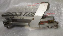
Hmm... I don't know much about electronics, but from the point of view of mechanics - what's wrong with hanging on thin wires? So the Soviet electronic level was made, which was probably copied from something. Here are some of his photos:

IMG_6727.JPG.bc2bb1bedb86830c2989d4637d807919.JPG

IMG_6729.JPG.c3a7df1b1559b62ac64c8ec854d5500a.JPG
 

rhb

Aluminum
Joined
Apr 27, 2019
Location
A small town in central Arkansas
I read lots of the thread, but couldn't figure out if anyone had succeeded. I also found a lot of photos of the inside of a Talyvel which I plan to study

Three pieces of 0.003" music wire should make a good semi-kinematic pendulum flexure. That will fix the core in a plane. It will move up and down slightly, but for +/- 0.01" range of motion that won't be a problem. Naturally it must have limit stops on the pendulum, but that's not difficult.

My Trans-Tek 216 LVDT (+/- 0.5") is too large for a Talyvel size instrument, but should be fine for a somewhat larger proof of concept. I bought the LVDT to play with because it was only $35 or so. And I've wanted one ever since I learned of them. So this is an excellent project to learn the basics.

An alternative that interests me is a ball bearing suspended by a single wire in a tube with capacitance bridges in X & Y. The same circuit that NASA used for the bubble based tiltmeter should easily handle the task. I bought some of the quad transistor arrays that NASA used. Because you can electronically calibrate by reversal one could use

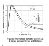
There are also optical proximity sensors which are very linear over a very narrow gap. I did some experiments several years ago. The particular sensor I tried wasn't good enough, but I found better ones. But got distracted and never ordered any.

I've attached an example of the distance vs current relationship for the first part I came to.. They are all remarkably linear around mid-range which for this one is 0.25 mm distance. My initial analysis suggests that a 12 bit ADC MCU with 4 sensors and a 1/2" ball bearing painted flat white on a 1" long, 0.003" diameter music wire flexure should deliver 1/2 arc second resolution over 30 minutes (+/- 15 minutes). The electronics are ~$10-15. The optical sensor the figure is from are < 50 cents each for a 1000 unit order. Under $2 in singles. A cheap MCU will do all the chores including recalibration by reversal.

Reg
 

Attachments

  • opt-sensor.png
    opt-sensor.png
    24.4 KB · Views: 3

John Garner

Titanium
Joined
Sep 1, 2004
Location
south SF Bay area, California
My inclination would be to follow the Grumman or Mahr/Federal pattern, which is discussed in depth in another PM thread.

As for Johansson's question, the Wyler "Blue" sensor is a flexure-suspended metal disc between sense electrodes.

Incidentally, I strongly recommend against using ambiguous symbolic unit identifiers such as the " symbol; in the interest of clear communications, spell out INCH or ARCSECOND.
 

TGTool

Titanium
Joined
Sep 22, 2006
Location
Stillwater, Oklahoma
I'm clearly missing a step so I hope someone will explain it for me. Rhb has at least twice mentioned that the level can be calibrated by reversal but I still don't get it. I can understand getting a zero by reversal, but without having a device, LVDT or other, that already specifies a calibrated change by displacement, I'm not sure how to tell with reversal what the unknown tilt of the surface plate is for a new device.
 

Milling man

Cast Iron
Joined
Aug 6, 2021
Location
Moscow, Russia
I can understand getting a zero by reversal, but without having a device, LVDT or other, that already specifies a calibrated change by displacement, I'm not sure how to tell with reversal what the unknown tilt of the surface plate is for a new device.
Making a device for level CALIBRATION is not at all difficult. In fact, you need a plate/plate with good flatness, two rollers with good accuracy, and flat gauge plates. Factory devices look something like this:

1.jpg
 

rhb

Aluminum
Joined
Apr 27, 2019
Location
A small town in central Arkansas
Calibration of angle vs displacement requires some gauge block comparisons and a bit of trigonometry. The reversal is for setting zero only. Sorry about not being clear.

NB I always try to follow " by of arc unless I mean inches and it's obvious from context that it is inches. But point taken.

FWIW I did some calculations based on the distance-current graph for the part I took the figure from with a 1/4 mm gap between the sensors and a pendulum on a 1" flexure. A 12 bit ADC would divide 0.020" into 4000 parts corresponding to 1 arc second (5 microinch displacement).

FWIW I've ordered a bunch of 1/2" steel grade 25 balls and 10 each of the best pair of optical sensors I could find for under $1 each. Next up is 0.003" music wire for the flexure.
 

John Garner

Titanium
Joined
Sep 1, 2004
Location
south SF Bay area, California
There's another electronic-lev technology that would be worth consideration, which is based on the "natural level" of a still fluid.

A century ago, that would be realized as an open dish of mercury. Some time later, that dish of mercury evolved into a closed dish with a Plano-parallel glass cover over a clear oil layer between the mercury and the glass.

By the late 1960s, Kern Instruments of Switzerland had replaced the mercury and oil with other fluids that 1) did not mix with each other, and 2) had significantly different indices of refraction. At first, an optical image was reflected off of the level-surface interface of the two fluids.

Then, a decade or so later, the optical image was replaced by a collimated beam of light that was reflected into a quad-cell photodetector.

Sometime after Kern Instruments was absorbed into Leica, the collimated beam was replaced by a multiple-reticle image that was reflected into a camera-type image sensor. The positions of the reflected reticle images were mapped into sensor-space, and image-processing software number-crunches the sensor-space coordinates into instrument-space tilt.

Leica sells their tilt-meter mainly into the geo technical world, which uses them for long-term monitoring.

I've personally used these tilt sensors -- as built into Kern DKM-2AC, Kern E2EC, Wild / Leica T-3000A, and Leica 5100A theodolites -- since the early 1980s to plumb the rotation axes of rotary tables and rotary positioners used for antenna testing. We held maximum-non-verticality tolerances of 5 arc seconds thousands of times over 40 years, and actually found the theodolites to be easier to use for the "off label" use than all of the electronic levels we had other than the Federal 432.
 

Milling man

Cast Iron
Joined
Aug 6, 2021
Location
Moscow, Russia
If I'm not mistaken, now (in the last about 10 years) it is possible to build a level of 5 μm/meter or a little less than 1 arc second has become possible with the help of ready-made elements. For example:
The datasheet indicates an accuracy of 0.001 degrees, but it is analog and in real use people have achieved many times greater accuracy.
 

rhb

Aluminum
Joined
Apr 27, 2019
Location
A small town in central Arkansas
@John Garner

Can you direct me to datasheets or brochures for those instruments? I've not been able to find any.

Wild-Heerburg which wants money for a PDF of the catalog :-(

I'd also appreciate an explanation of your procedure.

@Milling man
Unfortunately, that part is obsolete, though I did find some on ebay. The analog output around 0 is 280 mV/degree or 78 uV/arcsecond. That would reasonably provide 0.1 arcsecond from modest electronics.

Big question is $35 from China or $85 from US. Is the China part real?

However, that suggested a search which turned up these:


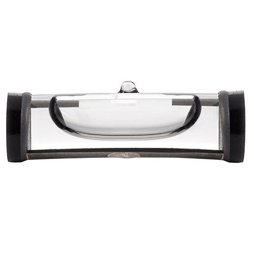
That sensor has a settling time of less than 500 ms, but stiction is still likely to be a problem. However, displacing the bubble might solve that apropos Robin Rennitz's solution for his CNC grinder.
 

Milling man

Cast Iron
Joined
Aug 6, 2021
Location
Moscow, Russia
Unfortunately, that part is obsolete, though I did find some on ebay.
I just tried to indicate the direction of the search :) I hope that I could somehow help.
With the help of such chips, several people have made at least experimental samples, which showed an accuracy in the region of + - 5-7 microns / m.
 

John Garner

Titanium
Joined
Sep 1, 2004
Location
south SF Bay area, California
rhb --

Today's version of the Leica Geosystems "Nivel" tiltmeter, which is based on the two-fluid "compensator" developed for the Kern DKM-2A theodolite, can be seen here: https://leica-geosystems.com/en-us/...stems/geotechnical-sensors/leica-nivel210_220 To the best of my knowledge, the Nivel has never been sold as an "electronic level" per se, but if it's not an electronic level it's the electronic level's kissingest cousin.

As I mentioned, Kern developed the two-fluid level for their DKM-2 second-order theodolite in the 1960s. In that use, it eliminated the need for a so-called "collimator level" that had long been used to compensate for residual errors in setting a theodolite's vertical (aka azimuth) axis vertical before making vertical-angle measurements. Automatic compensation proved to be both much more rapid than making manual adjustments with the collimator level screw, and proved to eliminate a fair number of human errors in making those manual adjustments.

Kern's new automatic-compensation theodolite, the DKM-2A (A signifying Automatic) was very well liked by surveyors doing geodetic work and by those doing industrial work. Kern eventually realized that the two-fluid compensator could also be used to quantify -- and subsequently correct analytically -- instrument plumbing error in the vertical plane perpendicular to the telescope line of sight, thus replacing the "striding level" that had been used historically.

Kern introduced a new variant of their second-order theodolite, the DKM-2AM, featuring a "trunnion-axis micrometer. I doubt that very many of the M-models were sold, I've only seen one in 42 years as an industrial surveyor.

With the advent of the "electronic" theodolite, Kern introduced an electronically-read version of the two-fluid level in their digital theodlites. The first version, the E-1, had only vertical-angle compensation, while the improved version, the E-2, featured automatic compensation of both vertical and horizontal angle measurement errors caused by residual plumbing errors .

In the mid 1980s, my employer bought its first electronic theodolite, a Kern E2EC (E meaning Erect image, C meaning equipped for bright-line autocollimation). At that time, we were using a digital electronic level model that was at the bleeding edge of its time's technology.

We had an urgent job that required a precisely-plumbed rotary table, and the digital electronic levels were flaking out. Our earlier-generation analog electronic levels were at launch base, and we couldn't find anyone locally who had an unused electronic level that we could borrow or rent. So, one of my fellow engineers came up with the idea of mounting an autocollimation mirror on the rotary table we needed to set up, and set up four theodolites on instrument stands so that they could be used to measure the mirror-normal zenith angle directions at the four cardinal rotary table positions.

Having done that, we calculated the average mirror-normal zenith angle, and adjusted the three Unisorb Lev-L-Line wedge jacks that supported the rotary table baseplate to bring the mirror-normal directions to the average position.

That technique worked, but it took several times the manpower and time that using electronic levels.

I wasn't in the hands-on crew, but in reviewing their data and discussing their process, I realized that the the E2EC theodolite could itself act as a digital electronic level.

One of the E2EC functions allowed the error measured by the two-fluid compensator to be displayed, in two perpendicular directions simultaneously. After rough leveling the rotary table surface (with a millwright level such as the Starrett 98) and then mounting and rough leveling the theodolite on the rotary table surface, we could set the theodolite horizontal pointing until the telescope and trunnion axes were orthogonal to the leveling wedge triangle.

From that point, it was a matter of 1) recording the tilt errors shown on the theodolite display, 2) rotating the rotary table 180 degrees and again recording the tilt errors shown on the theodolite display, and 3) calculating the average of the north/south and east/west tilt errors. At that point it became a simple matter of adjusting the leveling wedges until the theodolite display showed actual errors equal to the calculated average errors. Bingo.

Shortly after that, the same technique was modified for use with the single-axis compensator in the Kern DKM-2A theodolite. Then, a decade or so later, we further modified the technique to work with the Zeiss and Leica/Wild theodolites that were available at that time, the Kern instruments having been discontinued.

Ok, you asked.

Incidentally, the Wild-Heerbrugg website is -- or at least was -- a private website, not one operated by Leica Geosystems. As a huge fancier of Kern theodolites, I was very disappointed when Leica discontinued the Kern instruments, BUT Leica has been very good about supplying archived literature about long-discontinued products from their herd of former competitors.
 

rhb

Aluminum
Joined
Apr 27, 2019
Location
A small town in central Arkansas
Wow! Thank you so much!

With the autocollimator eyepiece option I have multiple reasons for wanting a theodolite.

I have a friend who is a surveyor and sells high end GPS based instruments. So lots of opportunity to get a good deal on a trade-in.

Would you be so kind as to give me a list ranked most desirable first of instruments which have the leveling feature?

Are autocollimation eypeices portable between theodolites or are they model specific?

Thank you again. You've taught me a lot. The fluid flat blows me away. I've long been familiar with the astronomical techniques, but not aware of the evolution of survey instruments.

Have Fun!
Reg
 

John Garner

Titanium
Joined
Sep 1, 2004
Location
south SF Bay area, California
Something that slipped my mind: ALWAYS check instrument stability. In my description of the technique we used to plumb the rotational axis of a rotary table (which also applies to an "azimuth positioner" used for antenna testing), there should be three sets of initial values, at positions of 0 degree, 180 degree, and 360 degree . . . unless the table won't go to a 360 degree position, in which case the third set should be after returning the table to 0 degree. If the first and third sets aren't very nearly identical, you need to find and fix an instability problem before messing around with adjustments.

I'd also suggest that the initial rough and fine adjustments be done with the machine-to-foundation holddowns loose, and then tighten the holddowns before final tweaking, using the leveling wedges to stretch the holddowns.

To answer your questions, I still consider the Kern DKM-2, the DKM-2A, and the E2EC to be my favorites, with the Wild T-3 and T-3000 to be runners up. The Hilger & Watts Microptic and the Jena second-order theodolites are also superb instruments, but I never used them enough to be able to reach for the right knob without having to think about it.

I would hesitate to buy an "electronic digital" theodolite for personal use simply because batteries and displays don't last forever, and plug-and-play replacement parts are both hard to find and expensive.

On to autocollimation. There are fundamentally two types of autocollimation systems. I prefer to call them "bright line" and "bright field". Others have termed them "false-" or "Gaussian autocollimation" and "true-" or "real autoccimation" respectively.

Bright line systems project a cross of light to a collimation mirror, the projected cross then reflected back into the telescope; the position of the returned image is compared to the telescope crosshair. Optically speaking, bright line autocollimation is more complex, and has more components to go wrong, but is much easier to use.

The bright field autocollimator backlights the telescope reticle, which casts a shadow that, after reflection from the mirror, looks like a reversed up/down & right/left reticle when viewed in the telescope. Bright field systems are simpler, and when properly pointed there cannot be an offset between the real and image articles, at the expense of usability.

Autocollimation eyepieces are, as far as I know, unique to each makers' instruments. Neither is there any assurance that autocollimation eyepieces made by any one maker will fit every instrument capable of autocollimation that maker makes.
 
Last edited:

fobyellow

Plastic
Joined
Mar 9, 2021
Hmm... I don't know much about electronics, but from the point of view of mechanics - what's wrong with hanging on thin wires? So the Soviet electronic level was made, which was probably copied from something. Here are some of his photos:

IMG_6727.JPG.bc2bb1bedb86830c2989d4637d807919.JPG

IMG_6729.JPG.c3a7df1b1559b62ac64c8ec854d5500a.JPG
thankyou for these pics, there are some intresting ideas!!! whats the resolution? how is the repeat?
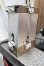
I tried myself following federal and talyvel, they are easy to achieve resolution better than 1um/m, but also easy to fail at repeat. the effective length of the pendulum is about 50mm, to achieve better than 1um/m repeat, the mass of the pendulum must repeat less than 0.02um. the suspending wires(or plates) are easy to reach to their elastic limit while move around the full stroke, one of my sample project finally reached 1um repeat while the stroke is limited to 200um/m.

default.jpg
 

fobyellow

Plastic
Joined
Mar 9, 2021
Resolution is 1um/m. Repeat..... This is not a very simple question)))) According to the reviews of people who have this level, the repeatability is about 2-4 microns per meter. More like around 2.
thats already very good!
could you pls tell me the model number, i want to find more about it
 

Milling man

Cast Iron
Joined
Aug 6, 2021
Location
Moscow, Russia
could you pls tell me the model number, i want to find more about it
This is a level from the Soviet Union, I don't think you will find any information about it. I haven't even been able to find instructions yet. The model is called Caliber 128. I have a photo of his wiring diagram in poor quality, but now it's all good only for a museum. On ready-made sensors, the levels turn out a little worse, but without problems - judging by the reviews. Just a few elements on the board and a cable, instead of a stack of electronic boards. Here is what my colleagues did with ready-made chips from the store:
№1, from Ukraine
post-22008-018430800_1543065706.jpg

post-22008-094347200_1544164850.jpg

№2, from Russia
Level:
post-51086-083448400%201393697215.jpg

adc:
post-51086-047208900%201393697216.jpg


Top