What's new
What's new

Harig 612 Spindle Sound

jwweathers

Aluminum
Joined
May 29, 2016
All,

I fired up my “new to me” Harig 612 spindle today. I am wondering how the spindle should sound. I’m not sure if it should be dead silent or what. See video linked below, and let me know if you have any thoughts.


Thanks!
Jeff
 

eKretz

Diamond; Mod Squad
Joined
Mar 27, 2005
Location
Northwest Indiana, USA
Ummmm.... yeah. Not good. Sounds like a rock troll gargling gravel.

Here's my Brown & Sharpe 818 - you can hear the spindle in the background. The sound isn't going to be silent but it should be smooth and fairly quiet running. Yours definitely sounds like it needs new bearings somewhere if nothing is rubbing on the spindle.

Is that direct drive or belt drive? If it's belt drive I'd pull the belts and see if it quiets down. If not, maybe the motor bearings are no good. If it does, spindle bearing replacement time.

 
Last edited:

jwweathers

Aluminum
Joined
May 29, 2016
Ummmm.... yeah. Not good. Sounds like a rock troll gargling gravel.

Here's my Brown & Sharpe 818 - you can hear the spindle in the background. The sound isn't going to be silent but it should be smooth and fairly quiet running. Yours definitely sounds like it needs new bearings somewhere if nothing is rubbing on the spindle.

Is that direct drive or belt drive? If it's belt drive I'd pull the belts and see if it quiets down. If not, maybe the motor bearings are no good. If it does, spindle bearing replacement time.

Mine is direct drive. I hear the sound, but it is definitely louder in the video than in person. It sounds like it’s coming from the very front of the spindle. I’m sure it is difficult to diagnose by ear. Nevertheless, I will look into new spindle bearings. I appreciate the suggestions.

Thanks!
Jeff
 

jwweathers

Aluminum
Joined
May 29, 2016
It sounds clunkity, but that can also be the motor or the drive.
Still, it should be fixed.
Agreed. I have been offered a Spindle/Motor Assembly at a reasonable price, so that is likely the simplest and best solution.

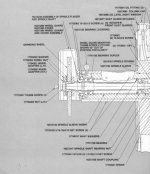
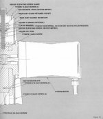
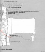
However, let’s say it’s the forward most bearing pair that are bad. That’s where the sound seems to be coming from. I wonder if it is possible to replace just those bearings without too much trouble (see pics).

This would be my first spindle rebuild, so I am a little apprehensive. All suggestions welcome.

Thanks!
Jeff

49607A72-C441-48CF-BEB2-52213C6F18B9.jpeg461C4243-C071-49B3-8AD1-B5775B79AD01.jpeg
 

mottrhed

Aluminum
Joined
Sep 23, 2013
Location
nh
Unloaded-and/or failed front angular contact bearings. These spindles are simple as far as spindles go, but if you are looking to hold tight tolerancing and get a good life out of the spindle I probably wouldn't recommend tackling it yourself.

But to directly answer your question, there is no way to replace the front bearings without taking the rear apart as well, which will likely damage the rear bearing..which you should replace if your there anyway. Make sure to check all critical dimensions while its apart, and check/set preload once its assembled and before you run it. Should have your runout on the OD taper well inside of .0001".
 

RJT

Titanium
Joined
Aug 24, 2006
Location
greensboro,northcarolina
Without knowing what the proper preload is supposed to be, and lacking the equipment to make the exact size shim or spacer that may be needed, I would vote for have a spindle repair shop replace bearings. There is more to it than just replacing the bearings. Precision measurement of end play and proper placement of shims or trimming spacers to take up that play is essential to the life of a precision spindle.
 

jwweathers

Aluminum
Joined
May 29, 2016
I won't argue against the idea that a professional rebuild is best, and I certainly appreciate the expert input. However, this machine will sit in my home shop and be used rather sparingly. Thus, I can't justify the cost. My Plan A is to install the Spindle/Motor Assembly that has been offered to me and hope that it is in good shape, will last, etc. Plan B is to tackle the spindle rebuild on my own and learn a few things.

Thanks!
Jeff
 

eKretz

Diamond; Mod Squad
Joined
Mar 27, 2005
Location
Northwest Indiana, USA
I would take plan A if you can. If that doesn't work out we can try to advise on the rebuild, but that is not an easy job to advise on at distance or for an inexperienced fellow to tackle.
 

jwweathers

Aluminum
Joined
May 29, 2016
I would take plan A if you can. If that doesn't work out we can try to advise on the rebuild, but that is not an easy job to advise on at distance or for an inexperienced fellow to tackle.
I sincerely appreciate the offer, and I will take you up on it if necessary.

Thanks!
Jeff
 

jwweathers

Aluminum
Joined
May 29, 2016
Even though I plan to replace the entire Spindle/Motor Assy, I’d like to disassemble mine to see what has failed. Any tips?? I have the assembly on a table, and I am having trouble deciding where/how hard to pull. I have backed out the set screw in the attached illustration but I’m not sure where to go from here.

Seems like I should be able to remove the fasteners attaching the motor to the spindle housing and slide the motor out with the spider. Then I might be able to press the spindle out of the front of the housing. Is that correct? If so, any clue how hard I’ll need to press?

Thanks!
Jeff

F22B6CC0-FF7F-460E-8B91-8FD529FB7144.jpeg
 
Last edited:

mottrhed

Aluminum
Joined
Sep 23, 2013
Location
nh
Should be 2 set screws holding the cartridge in. If the motor is still on you are going to have to pull it out the front. Take the grinding wheel off the hub then grab the hub and pull forward, shouldn’t be too hard.
Once it’s out, pull the hub then there’s a shaft nut on the front, remove that-pay attention may be LH. Then the front cover is bolted on, remove. In a press push the shaft out the rear, shouldn’t take a ton of force, just overcoming the interference on the inner races in the front. Now with the shaft out go to the rear and take off the coupling and rear shaft nut. Now strip the rear bearing and spring assembly. Next grab the housing and push your front bearings out from the back to the front.
I think that covers it off the top of my head. Any questions or issues don’t be shy.
 

jwweathers

Aluminum
Joined
May 29, 2016
Should be 2 set screws holding the cartridge in. If the motor is still on you are going to have to pull it out the front. Take the grinding wheel off the hub then grab the hub and pull forward, shouldn’t be too hard.
Once it’s out, pull the hub then there’s a shaft nut on the front, remove that-pay attention may be LH. Then the front cover is bolted on, remove. In a press push the shaft out the rear, shouldn’t take a ton of force, just overcoming the interference on the inner races in the front. Now with the shaft out go to the rear and take off the coupling and rear shaft nut. Now strip the rear bearing and spring assembly. Next grab the housing and push your front bearings out from the back to the front.
I think that covers it off the top of my head. Any questions or issues don’t be shy.
My Spindle/Motor Assy is held into place with 5 set screws. I have that out. Now, it looks like the spindle shaft has to come out of the front of the housing in the diagram. What am I missing?

Thanks!
Jeff
 

CarbideBob

Diamond
Joined
Jan 14, 2007
Location
Flushing/Flint, Michigan
Spindle cartridge attaches to motor with 4 allen bolts. (its a C face motor)
Motor is factory balanced to spindle after assembly so if you want to put it back together right you need to pull the motor straight out mark the "up" on the motor coupling and the spindle coupling so you can match them back up when putting back together.

Sounds like you have lost preload. This is controlled by the wave springs part# 17748701 in front of the REAR bearing.
Note that the front angular bearings are mounted in the same direction (tandem DT) so without this pulling force they are free to rattle around.
The rear bearing must float in it's hole for this to work. There is a section in the manual for testing this preload.
One should also be careful when side wheeling with back of the wheel on this machine not to overcome this preload.
harigpreload.jpg

When the cartridge is removed from the motor take off the rear spider coupling. Then remove the spanner nut part# 16213147 and the spindle shaft will pull out through the front.

This is a very easy spindle to rebuild but this problem has to be addressed and the price of the super precision bearings used will likely give you a heart attack.
Everything must be super clean and high quality (preferably filtered) spindle grease should be used.

Bob
 
Last edited:

jwweathers

Aluminum
Joined
May 29, 2016
Spindle cartridge attaches to motor with 4 allen bolts. (its a C face motor)
Motor is factory balanced to spindle after assembly so if you want to put it back together right you need to pull the motor straight out mark the "up" on the motor coupling and the spindle coupling so you can match them back up when putting back together.

Sounds like you have lost preload. This is controlled by the wave springs part# 17748701 in front of the REAR bearing.
Note that the front angular bearings are mounted in the same direction (tandem DT) so without this pulling force they are free to rattle around.
The rear bearing must float in it's hole for this to work. There is a section in the manual for testing this preload.
One should also be careful when side wheeling with back of the wheel on this machine not to overcome this preload.
View attachment 367664

When the cartridge is removed from the motor take off the rear spider coupling. Then remove the spanner nut part# 16213147 and the spindle shaft will pull out through the front.

This is a very easy spindle to rebuild but this problem has to be addressed and the price of the super precision bearings used will likely give you a heart attack.
Everything must be super clean and high quality (preferably filtered) spindle grease should be used.

Bob
You’re the man, Bob. This is consistent with how I thought the spindle would come apart based on the drawings.

One problem. I was very careful in separating the motor from the spindle cartridge, but I grazed the motor end of the spider and lost its position relative to the spindle half. Bummer.

Thanks!
Jeff
 

jwweathers

Aluminum
Joined
May 29, 2016
It's not crucial to align the same, just nice.
Since I need 3HP spindles I have replaced the motor without re-balancing and gotten away with.
Bob
Yeah, it seems like the large majority of imbalance would come from the motor. Hard to believe that anything but the slightest imbalance would come from the spindle shaft, bearing races, etc. makes sense it would be a “nice to have” rather than a “must have”.

Thanks!
Jeff
 

jwweathers

Aluminum
Joined
May 29, 2016
I was able to disassemble the Spindle/Motor Assembly without much trouble. A quick summary for reference assuming that the Grinding Wheel, Wheel Guard and Cover Assembly, etc. have already been removed (i.e. the Spindle Shaft taper is exposed).

1. Remove the 5 set screws locating the Spindle Sleeve in the Spindle Housing.
2. Slide the entire Spindle/Motor Assembly out of the rear of the column.
3. Remove the 4 allen bolts attaching the motor to the Spindle Housing.
4. Remove the motor from the rear of the Spindle Housing being careful to match the two halves of the Spider.
5. Remove the 4 allen screws attaching the Bearing Lockring to the Spindle Sleeve.
6. Press the Spindle Shaft from the rear of the Spindle Sleeve, and the remaining portion of the Spindle Assembly will come out of the front of the Spindle Sleeve.
7. Remove the Spindle Shaft Bearing Nut.
8. Slide the Bearing, Spindle Sleeve Insert, Duplex Bearings, and Bearing Lockring off the rear of the Spindle Shaft.

My appreciation to all for the tips! I hope this helps someone like me in the future.

Thanks!
Jeff
 

jwweathers

Aluminum
Joined
May 29, 2016
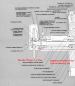
I've got the spindle shaft out with the Bearing Lockring, Spindle Flinger, Duplex Bearings, Spindle Sleeve Insert, Rear Bearing and Spindle Shaft Bearing Nut still attached. To dissemble the remaining hardware and replace the bearings, I have to remove the Spindle Shaft Bearing Nut. I have tried to remove it with a spanner wrench on the Spindle Shaft Bearing Nut while the other end (Bearing Lockring) is in a vice, see attached illustration, but I can't get it to budge. I scored the surface of the Bearing Lockring a bit in the process, and I don't want to do any major damage. Any ideas out there?

Thanks!
Jeff

1656612941026.png


Top