What's new
What's new

DoAll D10-30 Questions

Barry 16"

Plastic
Joined
Feb 26, 2017
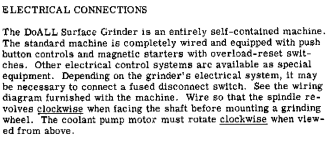
Hi all, I just purchased a 1961 (I think) DoAll D10-30 surface grinder and have to convert it from 440 to 220.
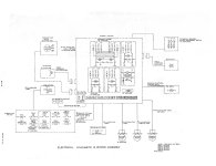
I bought a new rotary 3 phase convertor from American Rotary to run it but I am not an electrician so converting everything to 220 is a bit above my pay grade. I know how to change the motors to low voltage. So I am planning on eliminating the step down transformer in the electrical cabinet and just running 220 into it. I'll rewire the motors to low voltage. The 2 main concerns I have are :
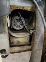
1) Which direction does the hydraulic pump/motor turn? as I may get direction wrong when wiring.
I would hate to spin wrong way and wreck hydro pump.
2) what voltage does my Selectron get? as near as I can tell it is model LV-24. Tag says DC 24 volts 240 AC.
does that mean that input is 220 single phase ? The last thing I want to do is smoke the Selectron controller.

any help would be greatly appreciated...Barry
 

Tongboy

Plastic
Joined
Oct 26, 2019
I'm working on a similar vintage d618-7 going from 480 to 240.

After my cursory run through of the electrical cabinet and the back of the spindle motor housing: It looks like the stepdown transformer needs to be switched from high voltage to low voltage. And then of course the 3 motors need to be swapped from high voltage to low voltage. It *looks* like all of the wires for the motors come back to the electrical panel so it should mean all the changes are done in the electrical box.

I've scoured the internet and haven't been able to find a wiring diagram for anything close. Best I've found are the two images below.

my selectron has a standard 120 plug on it. diagrams look to show it running off the first two legs in a 240v single phase setup.

PDF manual has a hookup section noting the direction of the spindle & coolant pump but doesn't look to mention hydraulic direction - assumingly you get the spindle going the right direction the hydraulic pump will also spin the right direction.

Good luck! would love to know how you end up tackling the motors.
 

Attachments

  • s-l1600.jpg
    s-l1600.jpg
    184.4 KB · Views: 14
  • s-l1600 (1).jpg
    s-l1600 (1).jpg
    196 KB · Views: 15
  • 2022-11-27_22h20_15.png
    2022-11-27_22h20_15.png
    134.5 KB · Views: 13

Barry 16"

Plastic
Joined
Feb 26, 2017
The transformer can be switched to low voltage ? That sounds like it may make things a bit easier. My thoughts exactly about the motor direction. If the spindle rotates in the rite direction; then the hydro should be turning in the rite direction.
 

Tongboy

Plastic
Joined
Oct 26, 2019
The transformer can be switched to low voltage ? That sounds like it may make things a bit easier.
yeah, mines setup for high voltage right now. H1 & H4 are two of the 3 phase input lines. H2 & H3 have a small black jumper.

To swap to low voltage take the H2-H3 jumper off and move it to H1-H2. Then make another jumper wire and hook it up H3-H4. You can then confirm that X1-X2 are ~120v.


I dug in to mine deeper today. Looks like the hydraulic pump is the only motor that brings all the wires back to the control box. The spindle motor & coolant pump will both need to be opened up and swapped to low voltage.
 

Barry 16"

Plastic
Joined
Feb 26, 2017
so if I make those changes to the transformer it will accept 220 input and have 220 output ? correct ? and you mean that the wires for the hydro pump all go into the electric cabinet so one would make the hi/low change in cabinet instead of in the motor cover ? that could be because there isn't any room to make changes while the motor is in the machine. Are you able to jog your hydro pump to see which direction it turns ?
 

Tongboy

Plastic
Joined
Oct 26, 2019
I was wrong - the spindle motor is the one that has all the wires running in to the box. The hydro pump in the base has a standard box on the motor.

If you take the little box off the front you'll see the hydro motor has a 'rotation' arrow. I took the fan assembly off the right hand side of the machine (6 flat heads) to get to the motor wire box. mine had a wiring diagram to swap to high/low - standard setup.

Spindle motor wiring was super simple. There were 3 wire nuts in the electrical box and 3 wires running to the wire connector length at the bottom of the box. Open the 3 nuts up wide and put the two wires in instead of one and wire nut the 3 other wires together.

I still need to dig in to my coolant pump (gusher 7p3, I pulled the cover off and found a high/low voltage diagram but only 3 wires... I need to go deeper in to that.

After swapping both motors over to low voltage I'm still fiddling with the transformer. I initially had one of the inbound wires as the generated 3rd leg of my phase converter. Even after swapping that over (swapped l3 & l2 on inbound) I'm still not seeing 120v on the low side of the transformer. I'll update once I figure out what I'm doing wrong.
 

Attachments

  • 20221129_173942.jpg
    20221129_173942.jpg
    635.2 KB · Views: 3

Tongboy

Plastic
Joined
Oct 26, 2019
h1-h3 & h2-h4 is the correct setup on the transformer. my apologies for the mistake.

After that everything fires right up
 

Attachments

  • 20221129_202319.jpg
    20221129_202319.jpg
    907.4 KB · Views: 11

Barry 16"

Plastic
Joined
Feb 26, 2017
h1-h3 & h2-h4 is the correct setup on the transformer. my apologies for the mistake.

After that everything fires right up
Looking at your diagram; it looks like it doesn't matter if incoming voltage is 220/380/440/or550 the selectron just gets L1 and L2 running to it. Are these 2 legs always going to be 220 single phase; or is the selectron that forgiving of what voltage goes into it ?
 

Barry 16"

Plastic
Joined
Feb 26, 2017
h1-h3 & h2-h4 is the correct setup on the transformer. my apologies for the mistake.

After that everything fires right up
Are we only supposed to end up with 110 coming out of the transformer to run all the switches and controls ? Is that all the transformer is used for ? Sorry to be asking so many possibly stupid questions but; I'm not an electrician, I'm a tool and cutter grinder. lol

Barry
 

Barry 16"

Plastic
Joined
Feb 26, 2017
My tag for selectron says 24 volts DC and 240 volts AC. So if needed I could just run 220 single phase into my electrical cabinet as well for it.
 

Tongboy

Plastic
Joined
Oct 26, 2019
Looking at your diagram; it looks like it doesn't matter if incoming voltage is 220/380/440/or550 the selectron just gets L1 and L2 running to it. Are these 2 legs always going to be 220 single phase; or is the selectron that forgiving of what voltage goes into it ?
I haven't tried wiring the selectron in yet. mine has a '120v' stamp on the right hand side so I suspect it needs to be fed from the low side of the transformer (wire 8 on the bus bar seems to be neutral, I haven't gone looking for low voltage elsewhere yet)

Are we only supposed to end up with 110 coming out of the transformer to run all the switches and controls ? Is that all the transformer is used for ? Sorry to be asking so many possibly stupid questions but; I'm not an electrician, I'm a tool and cutter grinder. lol
yes, the control voltage is all the 110v - as well as the overhead light and the downfeed assembly on top of the spindle. I think the selectron also is as I mentioned above (or at least mine is.)

don't feel bad, I'm a software guy figuring stuff out :D

My tag for selectron says 24 volts DC and 240 volts AC. So if needed I could just run 220 single phase into my electrical cabinet as well for it.
you can wire 2 of the 3 phases to your selectron if it says 240. If you are using a phase converter use the two non-generated legs.
 

Barry 16"

Plastic
Joined
Feb 26, 2017
h1-h3 & h2-h4 is the correct setup on the transformer. my apologies for the mistake.

After that everything fires right up
are the red and white wires coming off the transformer where the 110 v output is supposed to be ? and are the h1 and h4 terminals the 220v input ?
 

Tongboy

Plastic
Joined
Oct 26, 2019
are the red and white wires coming off the transformer where the 110 v output is supposed to be ? and are the h1 and h4 terminals the 220v input ?
yes, sir - red is hot 110v and when tested against the white/green you'll see ~120v when everything is working right.
 

Soldat17

Plastic
Joined
May 2, 2020
Hello, Tongboy and Barry 16. when you change the motor wiring from 440 v to 220 v remember to change the heaters in the motor control switches. While the 440 v heaters will usually run the motors changed to 220 v, the 440 v heaters are rated about one half the amps needed to run the 220 v motors at full load. You don't want the heaters to trip while grinding.
I have a Doall D824-12 with a Doall Selectron Model 210. Originally 440 v AC 220 V DC output to the 8" by 24" chuck 210 amps. This Selectron has a transformer inside it which has to be changed also. The transformer output has three different voltage taps. One high voltage which is rectified into the 220 v DC, a second tap that runs the timer motor for the demag cycle (110v ac), and a third tap of I think 5 v to power the 4 vacuum tubes that rectify the high voltage.
On the Selectron, be careful as these high DC voltages are extremly dangerous. They bite hard and don't let go.
Cheers
 

Tongboy

Plastic
Joined
Oct 26, 2019
Hello, Tongboy and Barry 16. when you change the motor wiring from 440 v to 220 v remember to change the heaters in the motor control switches.

On the Selectron, be careful as these high DC voltages are extremly dangerous. They bite hard and don't let go.
Cheers

Very good call out, thank you! I was fiddling with mine just yesterday with just the hydraulics figuring out the controls and it ran for about 10 minutes and then kicked the circuit, I knew exactly what it was once it did it.

I need to open up my selectron, it's stamped 120v on the outside and I wired it in as 110v off the transformer and it's working - it feels weak at full mag though... I don't mind fiddling with 3 phase but that high of voltage DC will keep me being VERY careful in there, thanks for highlighting that.

I ended up having to replace my coolant pump - it was only wired for high voltage. found a cheap replacement on ebay that is up and working.
 

Barry 16"

Plastic
Joined
Feb 26, 2017
I was thinking I would possibly have to replace the heaters as well. Thing is I don't know which ones to buy to replace them with. My Selectron seems to be different than both of yours. Mine says it is DC 24 volts and AC 240 volts, 100 watts. Mine seems to be a weird duck. It is model : LV
So I don't know if I should just run 220 v single phase into the Selectron. The electrical diagram shows just tapping off 2 legs of the 440 3phase to get the power; But I don't see how that would work to tap off 2 legs of 220 3phase. I'm thinking the voltage would be different. Thats why I'm thinking of just running a separate 220 single phase directly to the Selectron.


Top