1dogandnoexes
Aluminum
- Joined
- Jan 20, 2019
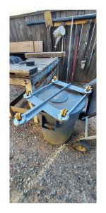
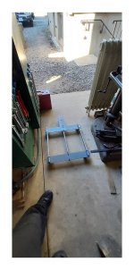
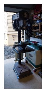
After much hemming and hawing, I finally decided to build a drill press mobile base. I don't yet have the space to park it in a corner, and until I have gotten a lot more organized in my small space, I will need to roll this behemoth in and out of the way many times. I'm putting this out there really as food for thought since the $400.00 in materials is unlikely to be justifiable in most settings.
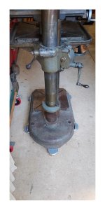
I deviated from the common design of having casters entirely outside of the footprint of the drill press for a few reasons. First, I wanted to reduce the tripping hazard created by having anything outside the plane of the original footprint. Second, I wanted to place the center of load point on the center of the caster to reduce leverage on the carriage holding the caster. Third, the round caster design meant that the carriage plates could be round instead of square.
The five casters have dual wheels that are "tread on steel core" casters with a 2 1/2" mount height, each with a 350 pound capacity. The flat steel is ¼" x 3 ½" 1018, the and three beams are ¼" x 1" mild steel.
I selected a weld free design so that the components could be removed and reused for other purposes after simple disassembly. I drilled, tapped, and chamfered qty (20) ¼ x 20 holes for the 5 casters, same for qty (14) ¼ x 20 taps to assemble the carriage, drilled qty (6) holes through holes in the ¼" steel plates, and drilled qty (8) holes through the 1" high mild steel. 4 of the holes through the plate were counter bored at a 1/16" depth 3/8" dia to permit the use of ultra low profile sockets screws. This eliminated a conflict with the drill press column and the fastener; I could have bolted the center beam up from the bottom but did not have the correct length fastener


 . I drilled, tapped, and chamfered qty (8) #10 x 32 holes through the sides of the upper beams for set screws which clamp the carriage down to the base of the drill press.
I takes a bit of a shove to get the press moving but I am pleased to say that it works.
I deviated from the common design of having casters entirely outside of the footprint of the drill press for a few reasons. First, I wanted to reduce the tripping hazard created by having anything outside the plane of the original footprint. Second, I wanted to place the center of load point on the center of the caster to reduce leverage on the carriage holding the caster. Third, the round caster design meant that the carriage plates could be round instead of square.
The five casters have dual wheels that are "tread on steel core" casters with a 2 1/2" mount height, each with a 350 pound capacity. The flat steel is ¼" x 3 ½" 1018, the and three beams are ¼" x 1" mild steel.
I selected a weld free design so that the components could be removed and reused for other purposes after simple disassembly. I drilled, tapped, and chamfered qty (20) ¼ x 20 holes for the 5 casters, same for qty (14) ¼ x 20 taps to assemble the carriage, drilled qty (6) holes through holes in the ¼" steel plates, and drilled qty (8) holes through the 1" high mild steel. 4 of the holes through the plate were counter bored at a 1/16" depth 3/8" dia to permit the use of ultra low profile sockets screws. This eliminated a conflict with the drill press column and the fastener; I could have bolted the center beam up from the bottom but did not have the correct length fastener


 . I drilled, tapped, and chamfered qty (8) #10 x 32 holes through the sides of the upper beams for set screws which clamp the carriage down to the base of the drill press.
I takes a bit of a shove to get the press moving but I am pleased to say that it works.

